
A vibration-insulating type composite-energy water heater

A composite energy, water heater technology, applied in solar collectors, water heaters/stoves, solar thermal energy, etc., can solve the problems of single energy source, inability to supply hot water and large vibration of water heaters, and achieve a single and smooth flow direction. Good heat exchange and vibration isolation effect, good economical effect

Inactive Publication Date: 2015-01-28
ZHEJIANG PROVINCE INST OF ARCHITECTURAL DESIGN & RES
View PDF8 Cites 1 Cited by
  • Summary
  • Abstract
  • Description
  • Claims
  • Application Information

AI Technical Summary

Problems solved by technology

[0005] The invention provides a shock-isolated composite energy water heater capable of recycling the heat released by earthen stoves and the sun and having good heat exchange and shock-isolation effects. way to ensure adequate hot water supply and large vibration problems

Method used


Image

  • A vibration-insulating type composite-energy water heater
  • A vibration-insulating type composite-energy water heater
  • A vibration-insulating type composite-energy water heater

Examples


Embodiment 1

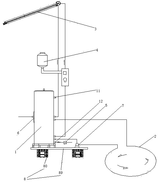
[0030] Embodiment one, see figure 1 , The shock-isolated composite energy water heater includes a water tank 1, a heating coil 2, a solar collector 3 and a shock-isolation frame 8.

[0031]The water tank 1 is also provided with a hot water outlet 11 and a cold water inlet 12 . A one-way valve 5 is installed in the cold water inlet 12 . The one-way valve 5 is opened toward the inside of the water tank 1 . An electric heater 6 is also provided in the water tank 1 . The electric heater 6 is used for heating the water in the water tank 1 .

[0032] Both ends of the heating coil 2 are connected with the water tank 1 . The heating coil 2 and the water tank 1 form a hot water circulation loop of the earth stove. A circulating water pump 7 is provided in the earth stove hot water circulation circuit.

[0033] The water inlet and outlet of the solar heat collector 3 are connected together with the water tank 1. The solar heat collector 3 and the water tank 1 form a solar hot wat...

Embodiment 2

[0039] Embodiment two, the difference with embodiment one is:

[0040] see Figure 5 , also includes oil replenishment mechanism 9.

[0041] see Image 6 , The circulating water pump 7 includes a pump casing 71 , a pump shaft 72 and a bearing 73 . The pump shaft 72 is rotatably connected in the pump housing 71 through a bearing 73 . The pump casing 71 is provided with an oil filling hole shaft hole 74 for oiling the bearing.

[0042] The oil replenishing mechanism 9 includes an oil storage tank 91 , an oil outlet channel 92 and a corrosive liquid storage tank 94 .

[0043] One end of the oil outlet passage 92 is provided with a filler nozzle 922 , and the other end is provided with an oil inlet bucket 921 . The filler nozzle 922 is butted together with the filler hole 74 . The oil inlet hopper 921 is located below the oil storage tank 91 . The filler nozzle 922 is lower than the oil storage tank 91 , that is, the oil in the oil outlet passage 92 can automatically flow i...

Embodiment 3

[0055] Embodiment three, see Figure 10 , the difference with the second embodiment is: the corrosive liquid storage tank 94 is provided with a wave-dissipating plate 941 floating on the corrosive liquid 97 in the corrosive liquid storage tank. The shell 951 passes through the wave breaking board 941 in a liftable manner along the up and down direction. The peripheral surface of the wave breaking plate 941 abuts against the side wall of the corrosive liquid storage tank 94 .


PUM


Abstract

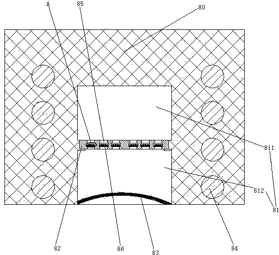
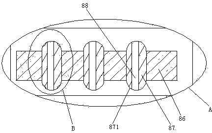
The invention relates to earthen stove water heaters, solves the problems of energy singleness and heavy vibration of water heaters, and particularly relates to a vibration-insulating type composite-energy water heater that is capable of recovering and reutilizing heat released by an earthen stove and the sun and has good heat exchange and vibration insulation effects. The composite-energy water heater comprises an earthen stove hot water circulation loop, a solar energy hot water circulation loop, and a vibration-insulating support, wherein the earthen stove hot water circulation loop comprises a water box and a heating coil, and the solar energy hot water circulation loop comprises the water box and a solar thermal collector. The earthen stove hot water circulation loop also comprises a circulation pump. The vibration-insulating support comprises a support body supporting the water box and the circulation pump, and rubber supporting feet. The bottom surface of each rubber supporting foot is provided with a liquid storage cavity and an insulation plate in the liquid storage cavity. Each insulation plate separates the corresponding liquid storage cavity into an upper liquid storage cavity and a lower liquid storage cavity and is provided with main damping channels communicating the corresponding upper liquid storage cavity and the corresponding lower liquid storage cavity. The main damping channels are provided with energy absorption plates. The energy absorption plates are provided with damping bars capable of sliding up and down. The damping bars are provided with branch damping channels. The lower end of each lower liquid storage cavity is provided with a U-shaped rubber cover arching towards the inside of the corresponding lower liquid storage cavity.

Description

technical field [0001] The invention relates to a water heater, in particular to a shock-isolation composite energy water heater. Background technique [0002] Existing water heaters include solar water heaters, electric energy water heaters and earthen stove water heaters etc. according to the difference of heat sources. The earth stove water heater is a water heater that uses the heat emitted by the earth stove to heat the water, and has the advantage of not consuming electricity, gas and other energy sources. A kind of soil stove water heater is disclosed in the patent document whose Chinese patent number is 2009201265540, the date of authorization announcement is December 16, 2009, and the name is called "earth stove water heater". The earth stove water heater in this patent document includes a water tank and a heating coil for absorbing the heat of the earth stove. The water inlet end of the heating coil is connected with the water tank, and the water outlet end of the...

Claims


Application Information

Patent Timeline
Patent Type & Authority Applications(China)
IPC IPC(8): F24C13/00F24J2/00
CPCF24C13/00F24S10/00Y02E10/44
Inventor 蒋纹钱杰黄笑冬
Owner ZHEJIANG PROVINCE INST OF ARCHITECTURAL DESIGN & RES
Learn More