
Severely-polluted soil remediation device

A soil remediation and heavily polluted technology, applied in the field of contaminated soil remediation and governance

Inactive Publication Date: 2015-01-28
CHANGZHOU UNIV
View PDF6 Cites 27 Cited by
  • Summary
  • Abstract
  • Description
  • Claims
  • Application Information

AI Technical Summary

Problems solved by technology

[0004] The technical problem to be solved by the present invention is: to overcome the technical problems of the above-mentioned patents, to provide a heavily polluted soil remediation device, which can effectively treat various volatile heavily polluted soils, has a simple structure, is easy to operate, and can perform soil restoration on the spot at the polluted site. repair governance

Method used


Image

  • Severely-polluted soil remediation device

Examples


Embodiment 1

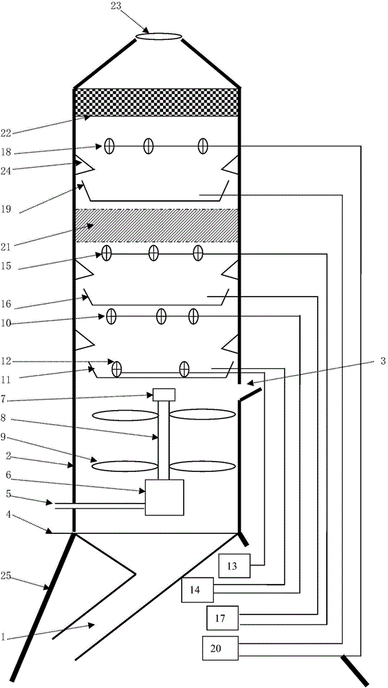
[0032] Such as figure 1 A heavily polluted soil remediation device of the present invention is shown, including soil addition and discharge system, soil heating and stirring system, volatile waste gas purification system; soil addition and discharge system, soil heating and stirring system are located in the entire heavily polluted soil remediation device The lower part of the volatile exhaust gas purification system is located in the middle and upper part of the entire heavily polluted soil remediation device.

[0033] The soil adding and discharging system comprises a soil discharging inclined bucket 1, a soil cylinder 2, and a soil adding port 3.

[0034] The soil discharge inclined bucket 1 is located at the lowest part of the soil addition and discharge system, the upper part of the soil discharge inclined bucket 1 is a conical structure, and the lower outlet is inclined to one side of the whole heavily polluted soil remediation device.

[0035] The lower part of the soil ...

Embodiment 2

[0055] The difference between the second embodiment of the present invention and the first embodiment is that the volatile substances in the soil are slightly alkaline, and there is no volatile waste gas alkalization absorption area in the heavily polluted soil remediation device, and the heavily polluted soil remediation device includes Soil addition and discharge system, soil heating and stirring system, volatile waste gas oxidation absorption area, volatile waste gas acidification absorption area, mist eliminator 21, activated carbon adsorption layer 22 and exhaust fan 23.

Embodiment 3

[0057] The difference between the third embodiment of the present invention and the first embodiment is that the volatile substances in the soil are slightly acidic, there is no volatile waste gas acidification absorption area in the heavily polluted soil remediation device, and the heavily polluted soil remediation device includes soil addition And discharge system, soil heating and stirring system, volatile waste gas oxidation absorption area, volatile waste gas alkalization absorption area, mist eliminator 21, activated carbon adsorption layer 22 and exhaust fan 23.


PUM


Abstract

The invention provides a severely-polluted soil remediation device. The severely-polluted soil remediation device comprises a soil adding and discharging system, a soil heating and stirring system and a volatile waste gas purification system, wherein the soil adding and discharging system comprises a soil discharging inclined hopper, a soil barrel and a soil adding opening; the soil heating and stirring system comprises an air inlet pipe, an air heating system, a stirring motor, a stirring transmission shaft and stirring blades; the volatile waste gas purification system sequentially comprises a volatile waste gas oxidization and absorption region, a volatile waste gas alkalization and absorption region, a demister, a volatile waste gas acidification and absorption region, an active carbon adsorption layer and an exhausting fan from bottom to top; or the volatile waste gas purification system sequentially comprises the volatile waste gas oxidization and absorption region, the volatile waste gas acidification and absorption region, the demister, the volatile waste gas alkalization and absorption region, the active carbon adsorption layer and the exhausting fan from bottom to top.

Description

technical field [0001] The invention relates to the technical field of remediation and treatment of polluted soil, in particular to a heavily polluted soil remediation device. Background technique [0002] The production processes of modern petroleum exploration, mining, processing enterprises, as well as chemical and pharmaceutical enterprises often cause serious pollution to the soil. The volatile substances such as diesel oil, benzene, toluene, and carbon tetrachloride in these heavily polluted sites are very high, and Most of these pollutants are hydrophobic organic substances, which have low solubility in the water phase and can stay in the soil environment for a long time, which not only destroys the structure and function of the soil, but also has a serious impact on the physical and chemical properties of the soil. Long-term source of contamination of groundwater. At present, the treatment of heavily volatile polluted soil mostly adopts digging the soil away from th...

Claims


Application Information

Patent Timeline
IPC IPC(8): B09C1/06B01D53/75B01D53/40B01D53/42
Inventor 万玉山陈艳秋黄利李定龙杨彦
Owner CHANGZHOU UNIV
Learn More