


Quick Research
Generate reliable direction feasibility study reports for your R&D in just a few steps.

Technical Q&A
Discover and master advanced knowledge NOW. Basics, ideas, possibilities, all at once.

Find Solutions
As an expert in R&D theories, this can generate solutions to your technical problems instantly.

Evaluate Feasibility
Analyze your overall solution with one click, know your potential R&D risks in advance.

Monitor Landscape
Get weekly tech updates, stay abreast of the latest tech innovations and key insights.
Manufacturing method of metal powder
A metal powder and manufacturing method technology, applied in the direction of plasma, electrical components, etc., can solve the problems of reduced manufacturing efficiency, deterioration, and plasma non-ignition, and achieve the effects of reducing the amount of contamination, improving life, and preventing material deterioration
- Summary
- Abstract
- Description
- Claims
- Application Information
AI Technical Summary
Problems solved by technology
Method used
Image


Examples
Embodiment 1
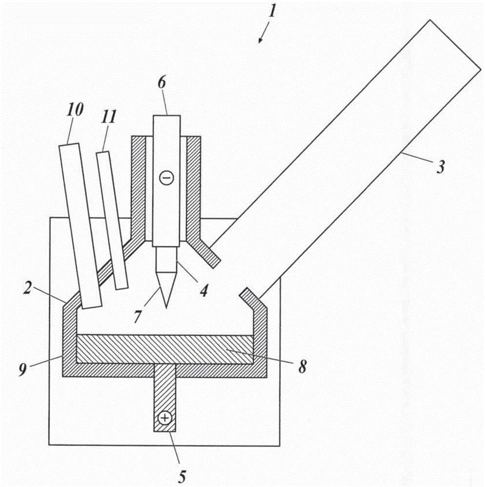
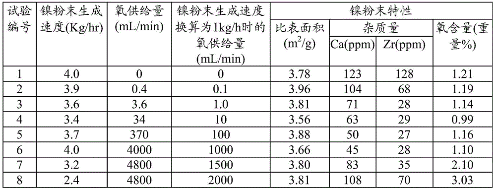
[0083] Into the reaction vessel of the above-mentioned plasma device with a supply rate of about 3.0-4.0Kg / hr, a metal nickel block as a metal raw material is supplied, and argon as a gas for generating plasma is supplied at a flow rate of 70 L / min, and argon is supplied at a flow rate of 630 to 630 L / min. Nitrogen as a diluent gas was supplied at 650 L / min, air was supplied so that the amount of oxygen was the flow rate shown in Table 1, and the device was operated for 500 hours at a plasma output of about 100 kW to produce nickel powder.
[0084] The production rate of nickel powder (supply rate of metal nickel lumps), the supply amount of oxygen into the reaction vessel, the specific surface area of the obtained nickel powder, the Ca content and Zr content as impurities, and the oxygen content are shown in the table together. 1.
[0085] It should be noted that the specific surface area of the powder was measured by the BET method, the Ca content and the Zr content were...
Embodiment 2
[0091] In order to dope nickel powder with sulfur, hydrogen sulfide (H 2 S) Nickel powder was produced in the same manner as in Example 1 except that the gas was supplied into the reaction container.
[0092] Table 2 shows the production rate of nickel powder (supply rate of metal nickel lump), the supply amount of oxygen into the reaction vessel, the specific surface area of the obtained nickel powder, the Ca content and Zr content as impurities, and the oxygen and sulfur content. . In addition, the sulfur content was measured with a carbon / sulfur measuring device (Horiba Manufacturing Co., Ltd. EMIA-320V).
[0093] [Table 2]
[0094]
[0095] From the results shown in Table 2, it was revealed that a significant impurity reduction effect was exhibited by supplying oxygen into the reaction container.
Embodiment 3
[0097]Into the reaction container of the above-mentioned plasma device, a metal copper block as a metal raw material was supplied at a supply rate of about 6.5 to 7.5 Kg / hr, and in order to dope copper powder with phosphorus, an oxygen supply part 11 was used together with air at a rate of 1 mL / hr. A copper powder was produced in the same manner as in Example 2 except that liquid triphenylphosphine was supplied into the reaction vessel at a speed of min (0.00419 mol / min).
[0098] Table 3 shows the production rate of copper powder (supply rate of metallic copper), the supply amount of oxygen into the reaction vessel, the specific surface area of the obtained copper powder, the Ca content and Zr content as impurities, and the oxygen and phosphorus content. In addition, the phosphorus content was measured with a fluorescent X-ray analyzer (Rigaku ZSX 100e).
[0099] [table 3]
[0100]
[0101] From the results shown in Table 3, it was revealed that a significant impurity r...
PUM
 Abstract
Description
Claims
Application Information
 - R&D Engineer
- R&D Manager
- IP Professional
- Industry Leading Data Capabilities
- Powerful AI technology
- Patent DNA Extraction
Browse by: Latest US Patents, China's latest patents, Technical Efficacy Thesaurus, Application Domain, Technology Topic, Popular Technical Reports.
© 2024 PatSnap. All rights reserved.Legal|Privacy policy|Modern Slavery Act Transparency Statement|Sitemap|About US| Contact US: help@patsnap.com