Picosecond Pulse Laser Oscillator

A laser oscillator and picosecond pulse technology, applied in the laser field, can solve the problems of increasing the instability of the resonator, the difficulty of adjusting the mode locking, and the increase of the loss of the resonator, etc., and achieve the convenience and repeatability of device installation and debugging Strong, stable oscillator performance

Active Publication Date: 2018-08-31
UNIV OF SHANGHAI FOR SCI & TECH
View PDF8 Cites 0 Cited by
  • Summary
  • Abstract
  • Description
  • Claims
  • Application Information

AI Technical Summary

Problems solved by technology

The all-fiber structure uses a polarization controller, and the integrating sphere modulation is performed by rotating the polarization controller knob. Since the polarization controller mixes 1 / 2 wave plate and 1 / 4 wave plate, it is slightly more difficult to adjust the mode locking, and each component is separated , which increases the instability of the resonator; the half-space half-fiber structure uses a fiber collimator to couple the optical path, adding 1 / 2 wave plate and 1 / 4 wave plate in the space part, polarization beam splitting crystal, through discrete modulation wave plate, The difficulty of mode locking is reduced, but due to the influence of the working distance of the fiber collimator and its coupling efficiency, the loss of the resonator will increase
The common deficiency of the two modes of locking lies in the stability of the resonant cavity structure. Due to external fluctuations, the optical fiber fluctuates, causing the resonant cavity to jitter, and the length of the resonant cavity changes, resulting in unstable mode locking.

Method used


Image

  • Picosecond Pulse Laser Oscillator
  • Picosecond Pulse Laser Oscillator
  • Picosecond Pulse Laser Oscillator

Examples


Embodiment Construction

[0033] The picosecond pulse laser oscillator of the present invention will be described in detail below with reference to the accompanying drawings. Those skilled in the art should understand that the embodiments described below are only illustrative illustrations of the present invention, and are not intended to limit it in any way. Throughout the drawings, the same reference numerals designate the same or similar parts.

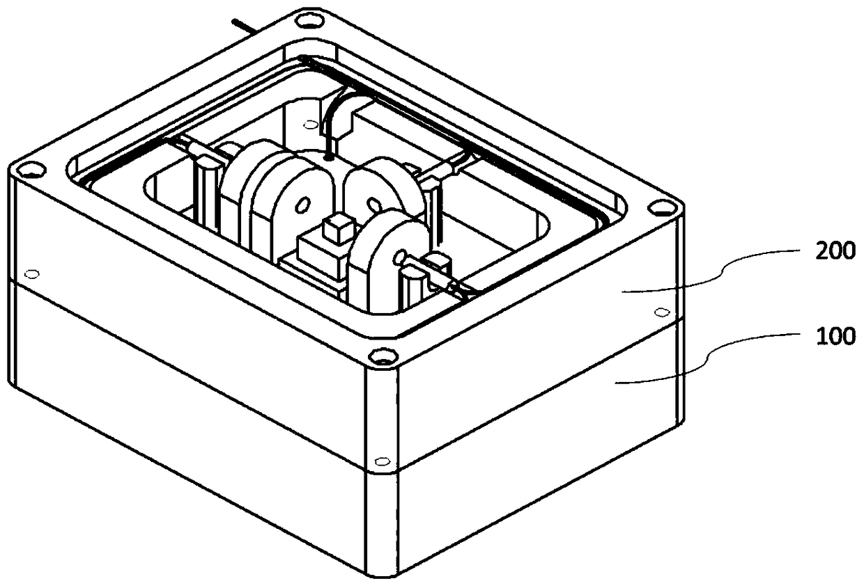
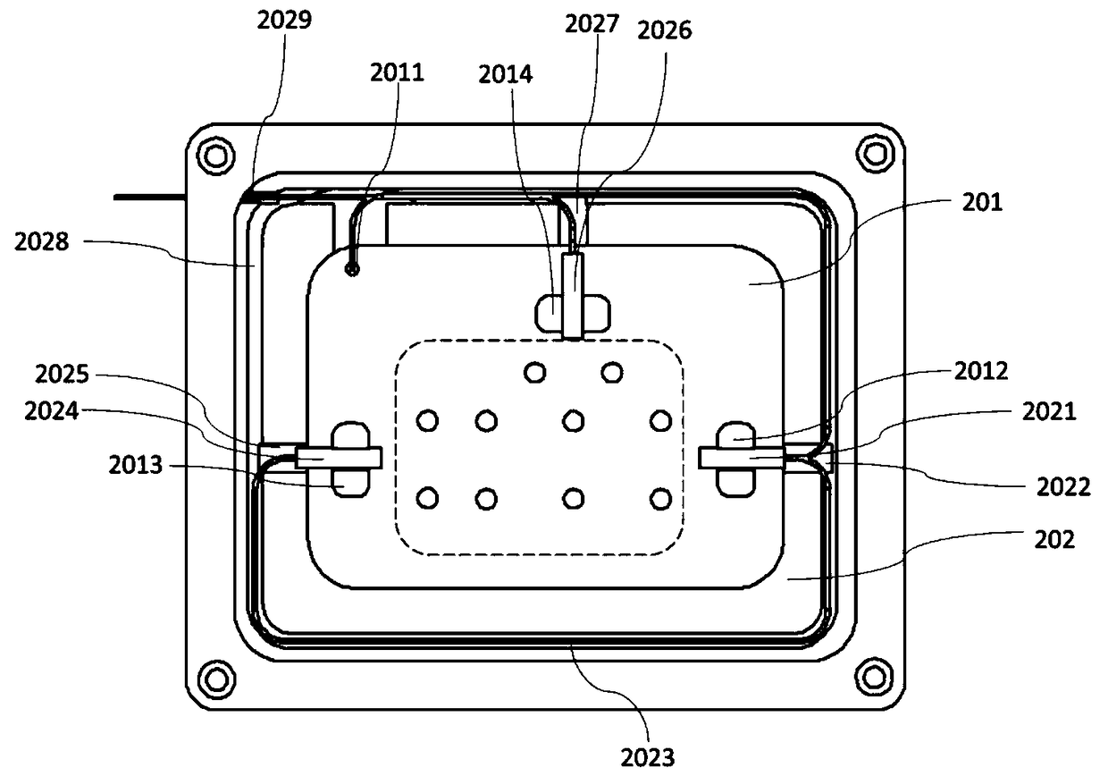
[0034] Figure 1 to Figure 5 A preferred embodiment of the picosecond pulsed laser oscillator of the present invention is shown. Such as figure 1 As shown, the picosecond pulsed laser oscillator includes a pump light generating module 100 and a laser generating module 200 . Preferably, the pump light generating module 100 and the laser generating module 200 are connected and fixed by fasteners.

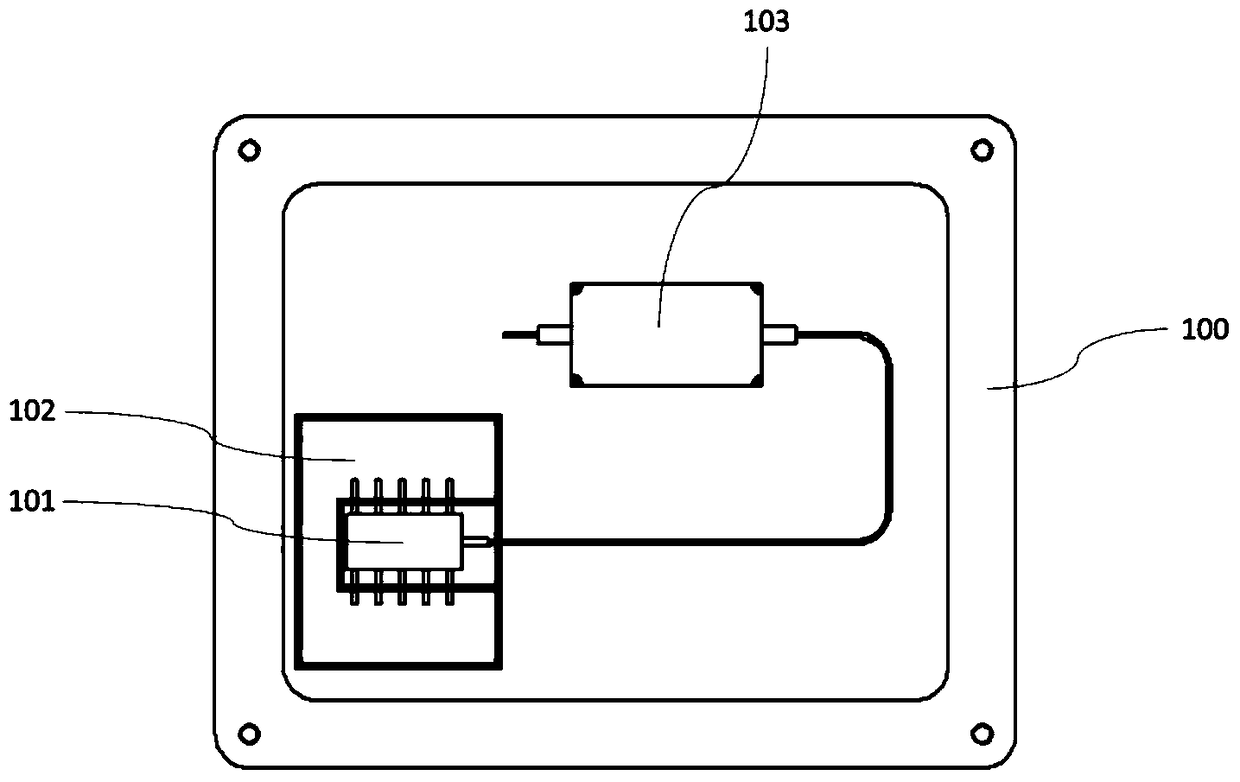
[0035] Specifically, such as figure 2 As shown, the pump light generating module 100 includes a laser diode 101, a driving circuit 102 and a pump isolator 10...


PUM


Abstract

The invention discloses a picosecond pulse laser oscillator which comprises a pump light generating module and a laser light generating module. The laser light generating module comprises a first optical fiber collimator and a second optical fiber collimator, wherein the first optical fiber collimator and the second optical fiber collimator are arranged in a resonant cavity and correspond to each other. A first 1 / 4 wave plate, a first 1 / 2 wave plate, a polarization beam splitting crystal and a second 1 / 4 wave plate are sequentially arranged between the output end of the second optical fiber collimator and the input end of the first optical fiber collimator. A second 1 / 2 wave plate and a third optical fiber collimator are sequentially arranged on a 90-degree reflection light path of the polarization beam splitting crystal in the resonant cavity. A first supporting column is fixedly arranged in the resonant cavity. A U-shaped groove is formed in the upper portion of the first supporting column. The front end of a cylindrical copper pipe of the first optical fiber collimator is positioned and fixed to the U-shaped groove in the first supporting column. A first semicylindrical notch groove corresponding to the first supporting column is fixedly formed in the surface of the middle layer of a shell. The tail end of the cylindrical copper pipe is positioned and fixed to the first semicylindrical notch groove in the plane of the middle layer. According to the picosecond pulse laser oscillator, large-scale industrial production can be achieved, and mold locking is stable.

Description

technical field [0001] The invention belongs to the field of laser technology, in particular to a picosecond pulse laser oscillator. Background technique [0002] Experiments have proved that picosecond pulsed lasers can perform high-precision micromachining on industrial materials such as metals, metal carbides, and silicon wafers. Compared with nanosecond pulses, picosecond pulses have a narrower pulse width, which can effectively reduce the thermal effect caused by laser radiation, and generate higher laser peak power, reaching the peak power density required for the ablation critical point of the material. More experiments and theoretical analysis show that the laser pulse width of about 10ps is suitable for many processing purposes. At the same time, the rapid development of fiber laser technology. Fiber laser light sources have shown many advantages, such as large surface area / volume ratio of gain medium, high average power, inherent fully enclosed flexible optical p...

Claims


Application Information

Patent Timeline
Patent Type & Authority Patents(China)
IPC IPC(8): H01S3/067H01S3/0941H01S3/13H01S3/098
Inventor 郝强张青山曾和平
Owner UNIV OF SHANGHAI FOR SCI & TECH
Why Eureka
Try Eureka