Eureka AIR delivers breakthrough ideas for toughest innovation challenges, trusted by R&D personnel around the world.

Fan coil cold measuring method based on flow-cold relation model

A technology of fan coil unit and metering method, which is applied in the direction of calculation, special data processing applications, instruments, etc., and can solve the problem of low failure rate of equipment

Inactive Publication Date: 2015-01-21
XI'AN UNIVERSITY OF ARCHITECTURE AND TECHNOLOGY
View PDF5 Cites 7 Cited by
  • Summary
  • Abstract
  • Description
  • Claims
  • Application Information

AI Technical Summary

Problems solved by technology

[0008] The purpose of the present invention is to propose a flow-based method applied to the cooling end of a fan coil unit, aiming at the common shortcomings of the existing cooling capacity measurement methods, especially the shortcoming of multi-point temperature measurement when performing cooling capacity measurement. The cold measurement method of the cooling capacity relationship model, on the premise of accurately measuring the cooling capacity and reasonably solving the common problems of the existing cooling capacity measurement methods, in particular, does not need to measure the temperature at multiple points, which makes the measurement more concise and reduces the equipment failure rate. Low cost, more convenient installation, conducive to energy saving, high reliability

Method used

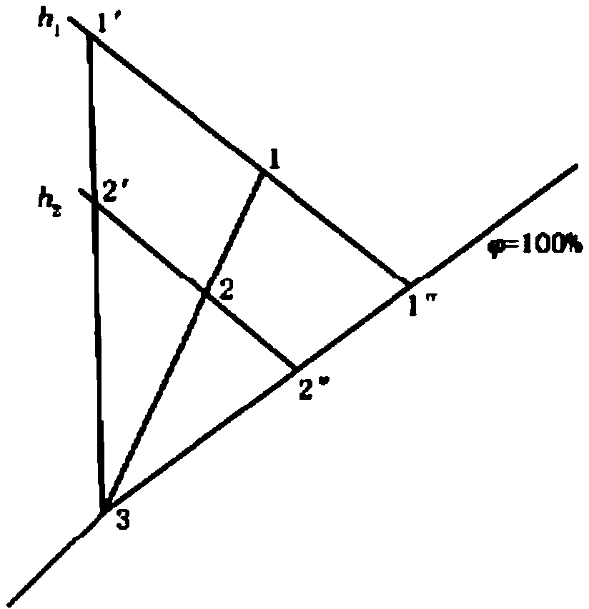

Image

  • Fan coil cold measuring method based on flow-cold relation model
  • Fan coil cold measuring method based on flow-cold relation model
  • Fan coil cold measuring method based on flow-cold relation model

Examples


Embodiment 1

[0253] This embodiment is mainly to illustrate the applicability of the present invention under different wind speed gear conditions:

[0254] (1) The model of the fan coil unit is FP-51; the structural parameters of the fan coil unit are: the tube row is 8×3 flat-sleeved tube type, the copper tube is 10×1mm, the length is 528mm, arranged in a regular triangle, the thickness of the aluminum fins and The spacing is 0.115mm and 2.35mm respectively, the vertical airflow direction tube spacing is 25mm, the ribbing coefficient is 14.5, and the windward area is 0.052m 2 , with a total heat transfer area of ​​6.76m 2 ;

[0255] (2) The air volumes of the high, medium and low levels are 510m respectively 3 / h, 390m 3 / h, 260m 3 / h;

[0256] (3) The water supply temperature is 13°C;

[0257] (4) The indoor air temperature is controlled at (28°C / 55%RH);

[0258] As mentioned above, due to the change of the water supply flow rate, the cooling capacity of the fan coil unit changes....

Embodiment 2

[0261] This embodiment is mainly to illustrate the applicability of the present invention under different indoor air setting states (temperature and humidity):

[0262] (1) The model of the fan coil unit is FP-51; the structural parameters of the fan coil unit are: the tube row is 8×3 flat-sleeved tube type, the copper tube is 10×1mm, the length is 528mm, arranged in a regular triangle, the thickness of the aluminum fins and The spacing is 0.115mm and 2.35mm respectively, the vertical airflow direction tube spacing is 25mm, the ribbing coefficient is 14.5, and the windward area is 0.052m 2 , with a total heat transfer area of ​​6.76m 2 , air volume 510m 3 / h;

[0263] (2) The water supply temperature is 13°C;

[0264] (3) The indoor air temperature is controlled at (28°C / 55%RH) and (26°C / 45%RH);

[0265] Under the above-mentioned different indoor air setting conditions (temperature and humidity), the cooling capacity of the fan coil unit changes with the flow rate as follo...

Embodiment 3

[0268] This embodiment is mainly to illustrate the applicability of the present invention under different water supply temperature setting conditions:

[0269] (1) The model of the fan coil unit is FP-51; the structural parameters of the fan coil unit are: the tube row is 8×3 flat-sleeved tube type, the copper tube is 10×1mm, the length is 528mm, arranged in a regular triangle, the thickness of the aluminum fins and The spacing is 0.115mm and 2.35mm respectively, the vertical airflow direction tube spacing is 25mm, the ribbing coefficient is 14.5, and the windward area is 0.052m 2 , with a total heat transfer area of ​​6.76m 2 , air volume 510m 3 / h;

[0270] (2) The indoor air temperature is controlled at (28°C / 55%RH);

[0271] (3) The water supply temperature is set to 7°C, 10°C, and 13°C respectively;

[0272] Under the above-mentioned different indoor air setting conditions (temperature and humidity), the cooling capacity of the fan coil unit changes with the flow rate...


PUM


Abstract

The invention discloses a fan coil cold measuring method based on a flow-cold relation model. According to a fan coil structure, air supply volume and water supply flow, an inside-outside surface heat exchange coefficient is determined, a heat transfer coefficient is determined, dew temperature of a fan coil is set according to water supply temperature, a heat exchange efficiency coefficient and a contact coefficient which the fan coil can provide are determined, dry condition corresponding to wet condition of inlet air of the fan coil is determined, a heat exchange efficiency coefficient which the fan coil requires to treat the air is determined, dry condition corresponding to wet condition of outlet air of the fan coil is determined, and finally, cold supply volume of the cold supply tail of the fan coil after flow measurement is acquired according to the principle of energy conservation. The method has the advantages that measuring a temperature difference between supplied heat and supplied backwater is not required, the operating process is simpler accordingly, equipment failure rate is low, mounting is more convenient, energy saving is favored, reliability is high, and field measurement data shows that the method is higher in accuracy.

Description

technical field [0001] The invention relates to the field of cooling capacity metering, in particular to a cooling capacity metering method based on flow metering which is mainly applied to the cooling end of a fan coil unit. Background technique [0002] The fan coil unit continuously recirculates the indoor air through the fan in the unit, so that the air is cooled (heated) after passing through the cold water (hot water) coil, so as to maintain a constant indoor air temperature. Fan coil unit is the ideal end of the central air-conditioning system. It is widely used in the fields of civil and industrial buildings in my country, and it is the most widely used cooling end. With the progress of heat metering work in our country, the energy saving effect obtained through metering is obvious. With the massive construction of high-end residential buildings in our country, the central air-conditioning system has been widely used in residential buildings, and the demand for cool...

Claims


Application Information

Patent Timeline
Patent Type & Authority Applications(China)
IPC IPC(8): G06F19/00
Inventor 王智伟闫清杨锋斌闫增峰
Owner XI'AN UNIVERSITY OF ARCHITECTURE AND TECHNOLOGY
Why Eureka
Eureka Blog
Learn More