
A Comprehensive Calibration Method of Interferometer Array

A calibration method and interferometer technology, which is applied in the direction finder using radio waves, the monitoring/testing of radio wave directional devices, etc., can solve the problem that the angle measurement correction algorithm is not given, and the azimuth and pitch of the interferometric angle measurement algorithm are not pointed out. Problems such as error coupling and error model inapplicability

Active Publication Date: 2017-04-12
XIAN INSTITUE OF SPACE RADIO TECH
View PDF3 Cites 0 Cited by
  • Summary
  • Abstract
  • Description
  • Claims
  • Application Information

AI Technical Summary

Problems solved by technology

When the method in this document is calibrated, it is first necessary to obtain the azimuth and elevation angles of the incident target through an optical telescope; secondly, the phase error considered in this document includes the length error of the first pair of antenna rotation arms, the rotation angle error, and the tilt error of the rotation plane. Since it has to go through three pairs of antennas successively, the transmission path model of the incident signal is different from that of general interferometers, so its error model is not suitable for general interferometers; the literature does not give a further angle measurement correction algorithm after obtaining the error term, and does not point out that in the interferometer How to Eliminate Azimuth and Elevation Error Coupling Problem in Angle Measurement Algorithm

Method used


Image

  • A Comprehensive Calibration Method of Interferometer Array
  • A Comprehensive Calibration Method of Interferometer Array
  • A Comprehensive Calibration Method of Interferometer Array

Examples


Embodiment approach

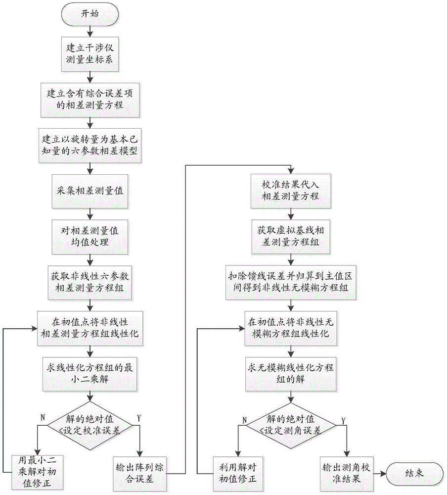
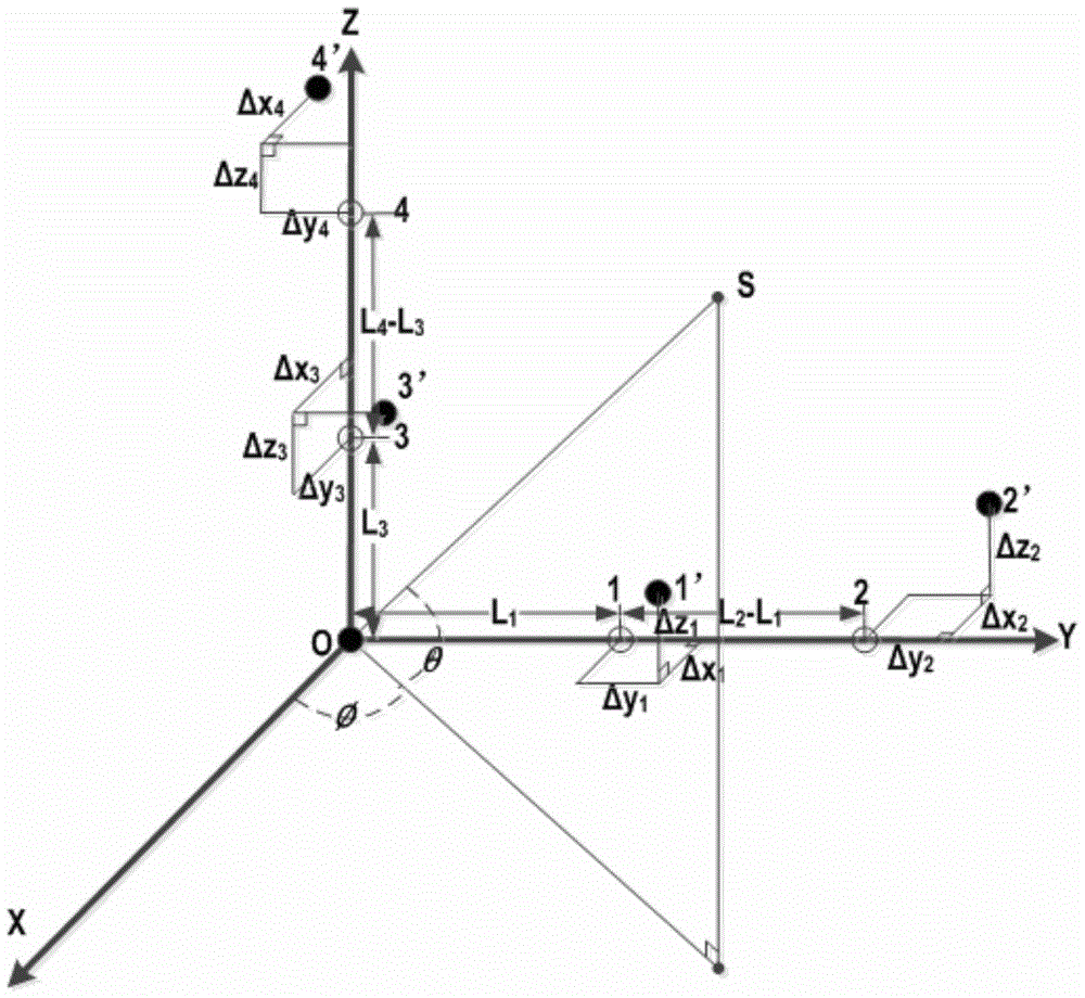
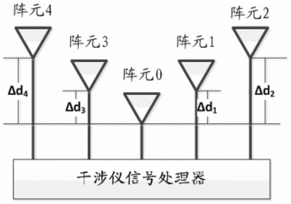
[0120] Attached below figure 2 , image 3 The shown 5-array element "L" type interferometer is taken as an example, and the present invention is described in further detail, as figure 1 The shown interferometer array comprehensive calibration method includes the stage of establishing an error model, obtaining the measurement equation stage, solving the error parameter stage and obtaining the angle measurement calibration result stage. The specific implementation is described as follows:

[0121] The steps to build the error model are as follows:

[0122] (1) Establish a measurement coordinate system on the interferometer array. exist figure 2 In the "L" type interferometer shown, the array element 0 on the interferometer array is selected as the origin O of the interferometer measurement coordinate system, the ideal azimuth baseline O2 is used as the Y axis, and the ideal pitch baseline O4 is used as the Z axis. The X-axis is determined by the law; the angle between the ...


PUM


Abstract

The invention provides an interferometer array integrated correction method. The method includes the steps of firstly, parameterizing a target signal initial incidence direction, a processing and installing comprehensive error and a feeder line passageway comprehensive error; secondly, obtaining a measuring equation set according to a known track rotation antenna array, and obtaining error parameters and incidence signal directions through parameter estimation; thirdly, modifying the error parameters into an interference angle measurement formula to obtain a precisely-corrected angle through the iteration technology. By means of the method, the incidence signal directions do not need to be accurately calibrated, the basic known quantities of the method are the rotation angle and the phase difference measurement value, the interferometer array processing and installing comprehensive error and the feeder line passageway comprehensive error can be obtained at the same time through parameter estimation, the problem that the direction error and the pitching error are coupled can be solved through the iteration technology when the angle measurement error correction is executed, and finally the precisely-corrected angle is obtained. The interferometer array integrated correction method is accurate in error model, simple in execution process, high in correction precision and capable of improving the correction efficiency and the angle measurement accuracy of an interferometer.

Description

technical field [0001] The invention relates to a comprehensive calibration method of an interferometer array, which is applied in the direction finding and positioning of radiation sources and belongs to the field of radio direction finding. This technology has been widely used in radar, sonar, mobile communication, geophysical exploration and other fields. Especially in electronic countermeasures, the interferometer can accurately locate the target in time. Background technique [0002] The basic principle of interferometer direction finding is to calculate the incident angle of the source by measuring the phase difference between the radiation source and the different array elements of the interferometer. At present, with the improvement of the working frequency band of the radiation source, in order to ensure the accuracy of interferometric measurements, strict requirements must be put forward for the phase consistency of each array element of the interferometer, the pro...

Claims


Application Information

Patent Timeline
Patent Type & Authority Patents(China)
IPC IPC(8): G01S3/02
CPCG01S3/023
Inventor 踪念科张蓬钟兴旺王登峰杨瑞强蔡春贵
Owner XIAN INSTITUE OF SPACE RADIO TECH
Learn More