Airtight test method for pressure refueling pipeline of aircraft wing fuel tank
A wing oil tank and test method technology, applied in the liquid tightness measurement using liquid/vacuum degree, by detecting the appearance of fluid at the leakage point, and by measuring the increase and deceleration rate of the fluid, etc., can solve the hidden danger of leakage and difficult system Air tightness test, threats to flight safety and other issues to achieve the effect of ensuring flight safety and eliminating hidden dangers of leakage
- Summary
- Abstract
- Description
- Claims
- Application Information
AI Technical Summary
Problems solved by technology
Method used
Image
Examples
Embodiment 1
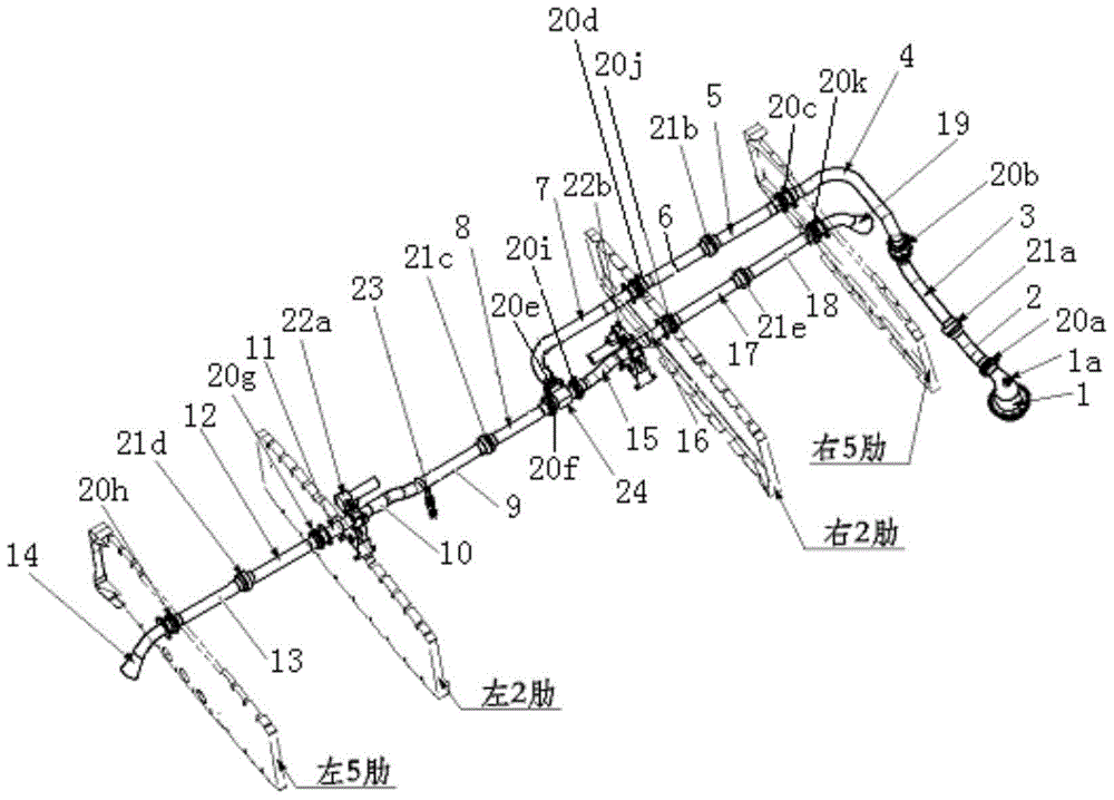
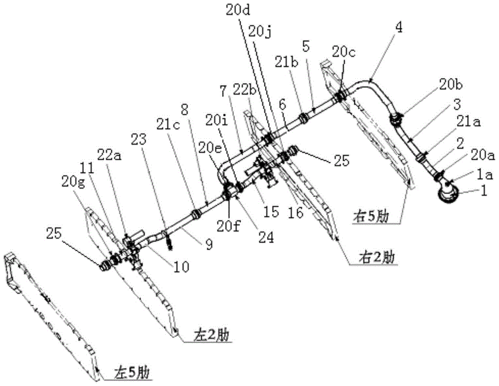
[0022] Connect the pressure refueling joint 1 to the test air source with a pressure gauge, turn on the air intake switch of the test air source, gradually increase the pressure to 1.242Mpa, then cut off the air intake switch of the test air source, keep the pressure for 5 minutes, and the pressure gauge If the indicated value does not drop, it means that there is no leakage in the pressure refueling pipeline, and the airtight test of the pressure refueling pipeline in the wing fuel tank is over.
Embodiment 2
[0024] Connect the pressure refueling joint 1 to the test air source with a pressure gauge, turn on the air intake switch of the test air source, pressurize to 1.242Mpa, then cut off the air intake switch of the test air source, and keep the pressure for 5 minutes. The indication value of the medium pressure gauge drops, indicating that there is leakage in the pressure refueling pipeline. At this time, use a brush dipped in neutral soapy water to smear on the connection parts in turn to check the leaking parts; during the inspection, it is found that the flexible joint 21c is leaking, and the flexible joint 21c is decomposed. If the sealing ring is found to be damaged at the joint, replace the sealing ring. Carry out the airtightness test of the pressure refueling pipeline of the wing fuel tank according to the method described in step 1. Keep the pressure for 5 minutes. If the indication value of the pressure gauge does not drop, it means that there is no leakage in the pressur...
Embodiment 3
[0026] Connect the pressure refueling joint 1 to the test air source with a pressure gauge, turn on the air intake switch of the test air source, pressurize to 1.242Mpa, then cut off the air intake switch of the test air source, and keep the pressure for 5 minutes. The indication value of the medium pressure gauge drops, indicating that there is a leak in the pressure refueling pipeline. At this time, use a brush to dip in neutral soapy water to smear on the connecting parts in sequence. Smear soapy water on the conduits one by one. Check that there is air leakage at the welding bead of the conduit. Decompose the leaking parts and repair them. After the parts are repaired, perform the airtightness test of the pressure refueling pipeline of the wing fuel tank according to the method described in step 1. Keep the pressure for 5 minutes, if the indication value of the pressure gauge does not drop, it means that there is no leakage in the pressure refueling pipeline, and the airtig...
PUM
 Abstract
Description
Claims
Application Information
 - R&D Engineer
- R&D Manager
- IP Professional
- Industry Leading Data Capabilities
- Powerful AI technology
- Patent DNA Extraction
Browse by: Latest US Patents, China's latest patents, Technical Efficacy Thesaurus, Application Domain, Technology Topic, Popular Technical Reports.
© 2024 PatSnap. All rights reserved.Legal|Privacy policy|Modern Slavery Act Transparency Statement|Sitemap|About US| Contact US: help@patsnap.com


