
A pneumatic in-mold riveting device

An in-mold riveting and pneumatic technology, which is applied in the field of pneumatic in-mold riveting devices, can solve the problems of increasing costs and rising product prices, and achieves the effects of cost saving, product price reduction and overall structural reliability.

Active Publication Date: 2016-06-15
INTERPLEX SUZHOU PRECISION ENG LTD
View PDF5 Cites 0 Cited by
  • Summary
  • Abstract
  • Description
  • Claims
  • Application Information

AI Technical Summary

Problems solved by technology

For the above two forms of product riveting, it is usually processed by a separate riveting mold, which requires special riveting molds, equipment, production workers and production sites, which greatly increases the cost and increases the product price.

Method used


Image

  • A pneumatic in-mold riveting device
  • A pneumatic in-mold riveting device
  • A pneumatic in-mold riveting device

Examples


Embodiment Construction

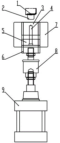
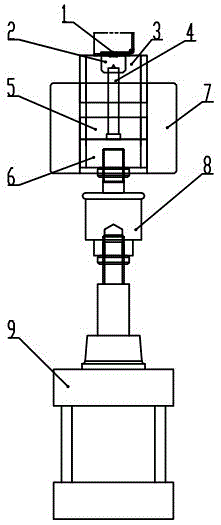
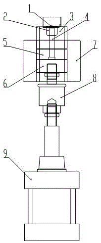
[0016] Such as Figure 1~3 The pneumatic in-mold riveting device shown includes a driving assembly, which is different in that: a backing plate 6 is connected to the driving assembly used in the present invention. Specifically, a fixing plate 5 is connected to the backing plate 6 , and a riveting punch 4 is connected to the fixing plate 5 . At the same time, a stripper 3 is connected to the riveting punch 4 , and a bending punch 2 is distributed above the stripper 3 . Moreover, riveting working ends 1 are distributed on the bending punch 2 .

[0017] As far as a preferred embodiment of the present invention is concerned, a floating coupling 8 is installed between the driving assembly and the backing plate 6 . Simultaneously, in order to improve the working efficiency of driving, the driving assembly is an air cylinder 9 . Of course, in order to assist in positioning the installation position of the riveting punch 4 , a fixing plate 5 is provided on the backing plate 6 . Mo...


PUM


Abstract

The present invention involves a kind of pneumatic internal riveting device, including a driver component. It is characterized by: a pad plate connected to the driver component, and a fixed plate is connected to the pad.At the same time, the riveting jumping head is connected to the seasoning board, and the bending head is distributed above the removing board. The riveting works on the bending head are distributed.As a result, the product can be riveted at the same time during the process of stamping products inside the mold, eliminating a separate riveting process.Then save costs and reduce product prices.At the same time, the overall structure is reliable and flexible, which can ensure product quality and improve production efficiency.

Description

technical field [0001] The invention relates to a riveting device, in particular to a pneumatic in-mold riveting device. Background technique [0002] Riveting is a common connection method on metal stamping products. There are two forms of general product riveting: 1. Riveting between two bending edges of a single product itself, 2. Riveting between two products. For the above two types of product riveting, it is usually processed by a separate riveting mold, which requires special riveting molds, equipment, production workers and production sites, which greatly increases the cost and increases the product price. Contents of the invention [0003] The object of the present invention is to provide a pneumatic in-mold riveting device in order to solve the above-mentioned problems in the prior art. [0004] The purpose of the present invention is achieved through the following technical solutions: [0005] A pneumatic in-mold riveting device, including a drive assembly, wh...

Claims


Application Information

Patent Timeline
Patent Type & Authority Patents(China)
IPC IPC(8): B21D39/00B21D22/00
Inventor 曹昌强杨曩顾月松
Owner INTERPLEX SUZHOU PRECISION ENG LTD
Learn More