
A mechanical in-mold riveting device

An in-mold riveting and mechanical technology, applied in the field of mechanical in-mold riveting devices, can solve the problems of rising product prices and increasing costs, and achieve the effects of reducing product prices, saving costs, and reducing costs

Active Publication Date: 2016-06-15
INTERPLEX SUZHOU PRECISION ENG LTD
View PDF4 Cites 0 Cited by
  • Summary
  • Abstract
  • Description
  • Claims
  • Application Information

AI Technical Summary

Problems solved by technology

For the above two forms of product riveting, it is usually processed by a separate riveting mold, which requires special riveting molds, equipment, production workers and production sites, which greatly increases the cost and increases the product price.

Method used


Image

  • A mechanical in-mold riveting device
  • A mechanical in-mold riveting device
  • A mechanical in-mold riveting device

Examples


Embodiment Construction

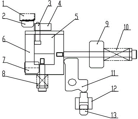
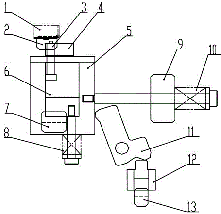
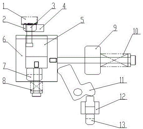
[0015] Such as Figure 1~3 The shown mechanical in-mold riveting device includes a bending punch 2, which is different in that a stripping plate 4 is provided on one side of the bending punch 2 used in the present invention, and the stripping The plate 4 is connected with a riveting punch 3, and the riveting punch 3 is connected with a riveting punch fixing plate 5. At the same time, a main sliding assembly is arranged on the periphery of the fixing plate 5 of the riveting punch. Specifically, the main sliding assembly used includes a main sliding block 6 , and a main reset assembly is arranged at the bottom of the main sliding block 6 . In addition, auxiliary reset assemblies are distributed on the side of the slider, and the sliding working surface of the main slider 6 is connected with an auxiliary sliding assembly through a push rod 11 .

[0016] As far as a preferred embodiment of the present invention is concerned, in order to facilitate the reset of the movement traje...


PUM


Abstract

The invention relates to a mechanical in-mold riveting device, which includes a bending punch. With riveted punch fixing plate. At the same time, a main sliding assembly is arranged on the periphery of the fixing plate of the riveting punch, the main sliding assembly includes a main slider, and a main reset assembly is arranged at the bottom of the main slider. In addition, auxiliary reset components are distributed on the side of the main slider, and the sliding working surface of the main slider is connected with auxiliary sliding components through push rods. As a result, the product can be riveted together during the process of stamping the product inside the mold, eliminating the need for a separate riveting process, thereby saving costs and reducing product prices. At the same time, the mold structure is reliable and flexible, which can ensure product quality, low cost and high efficiency.

Description

technical field [0001] The invention relates to a riveting device, in particular to a mechanical in-mold riveting device. Background technique [0002] Riveting is a common connection method on metal stamping products. There are two forms of general product riveting: 1. Riveting between two bending edges of a single product itself, 2. Riveting between two products. For the above two types of product riveting, it is usually processed by a separate riveting mold, which requires special riveting molds, equipment, production workers and production sites, which greatly increases the cost and increases the product price. Contents of the invention [0003] The object of the present invention is to provide a mechanical in-mold riveting device in order to solve the above-mentioned problems in the prior art. [0004] The purpose of the present invention is achieved through the following technical solutions: [0005] A mechanical in-mold riveting device, including a bending punch, ...

Claims


Application Information

Patent Timeline
Patent Type & Authority Patents(China)
IPC IPC(8): B21D39/00B21D22/00
Inventor 曹昌强杨曩顾月松
Owner INTERPLEX SUZHOU PRECISION ENG LTD
Learn More