Pay-off rack

A pay-off stand and cross technology, applied in the field of pay-off stand, can solve the problems of material loss, the diameter of the turntable cannot be adjusted, the pay-off stand cannot meet the requirements of use, etc., to avoid material loss and increase stability.

Inactive Publication Date: 2014-12-24
STATE GRID CORP OF CHINA +3
View PDF8 Cites 9 Cited by
  • Summary
  • Abstract
  • Description
  • Claims
  • Application Information

AI Technical Summary

Problems solved by technology

In the pay-off stand in the prior art, the diameter of the turntable is fixed and cannot be adjusted. If the diameter of the cable reel on the turntable needs to be increased, this pay-off stand cannot meet the requirements of use.
If there are many cables to be recovered, because the diameter of the turntable of the pay-off rack is fixed, the cables can only be disconnected, the cables on the turntable are removed, and the remaining cables are recovered by the pay-off rack, which will cause unnecessary material loss

Method used


Image

  • Pay-off rack
  • Pay-off rack
  • Pay-off rack

Examples


Embodiment 1

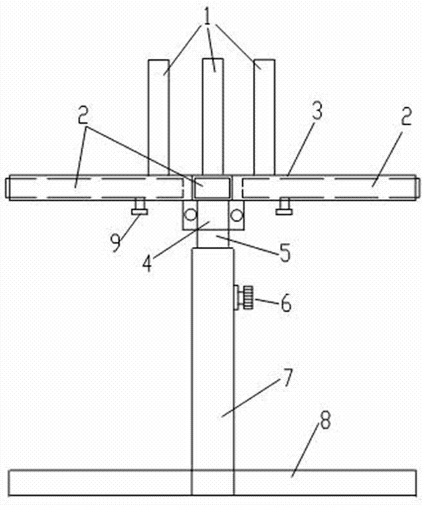
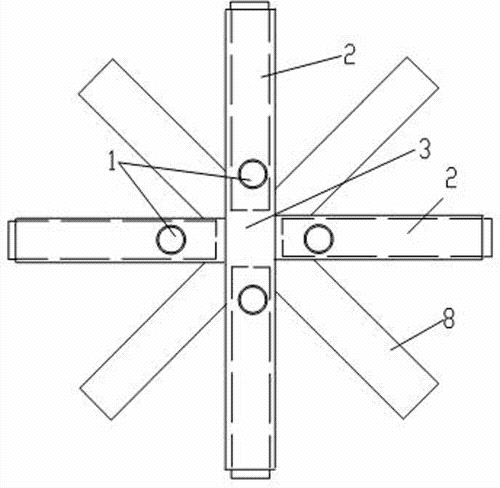
[0014] Embodiment 1: A pay-off rack, including a turntable 3, a lifting rod 5, and a vertical tube 7 with a base 8; the turntable 3 is a cross made of a pipe with a rectangular section, and is respectively set in four pipes of the cross The drawing tube 2 with a rectangular cross-section is provided with a vertical shaft tube 1 on the top surface of the cross, and the upper end of the lifting rod 5 is connected to the center of the bottom of the turntable 3 through a bearing 4, and the lower end of the lifting rod 5 is inserted into the vertical tube 7, the screw 6 that can fasten the lifting rod 5 is provided on the vertical tube 7 wall. The bottom surfaces of the four pipes of the cross are respectively provided with chute holes, and the lower part of the drawing pipe 2 is provided with fastening screws 9 which can move along the chute holes. There are four vertical shaft tubes 1 and they are evenly distributed on the top surface of the rotating disk 3 . The base 8 is a P-s...

Embodiment 2

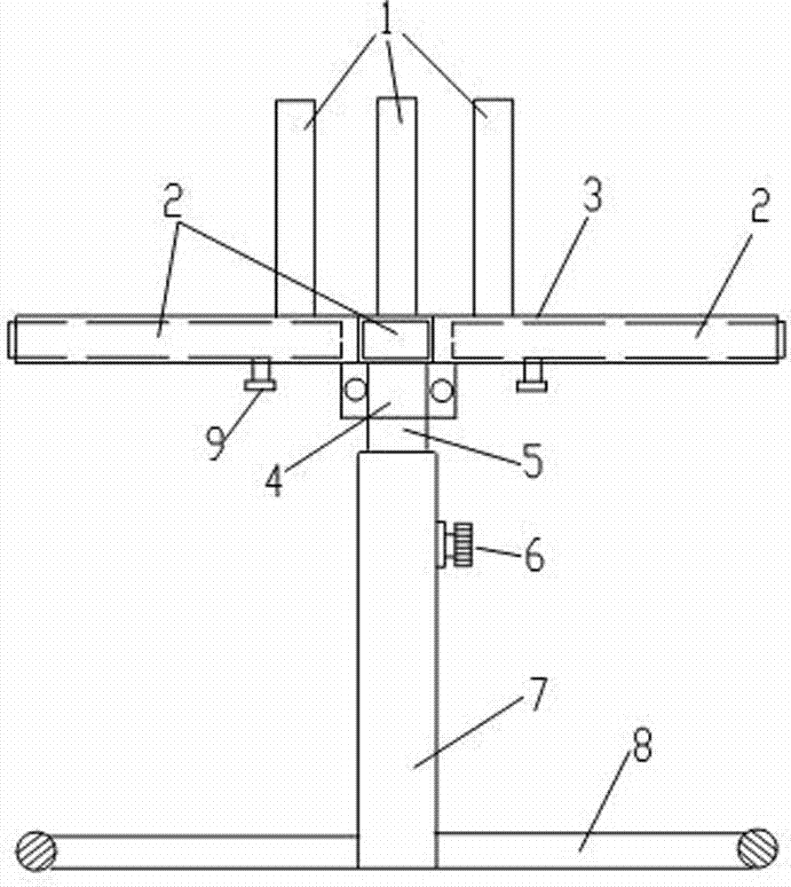
[0015] Embodiment 2: A pay-off rack, including a turntable 3, a lifting rod 5, and a vertical tube 7 with a base 8; the turntable 3 is a cross made of a pipe with a rectangular section, and is respectively set in four pipes of the cross The drawing tube 2 with a rectangular cross-section is provided with a vertical shaft tube 1 on the top surface of the cross, and the upper end of the lifting rod 5 is connected to the center of the bottom of the turntable 3 through a bearing 4, and the lower end of the lifting rod 5 is inserted into the vertical tube 7, the screw 6 that can fasten the lifting rod 5 is provided on the vertical tube 7 wall. The bottom surfaces of the four pipes of the cross are respectively provided with chute holes, and the lower part of the drawing pipe 2 is provided with fastening screws 9 which can move along the chute holes. There are four vertical shaft tubes 1 and they are evenly distributed on the top surface of the rotating disk 3 . The base 8 is a rin...


PUM


Abstract

The invention discloses a pay-off rack, and belongs to the technical field of cable laying tools. The pay-off rack comprises a turntable, a lifting rod and a vertical barrel with a base. The turntable is a cross made of pipes with rectangular sections, drawing pipes with rectangular sections are respectively nested in the four pipes of the cross, vertical shaft pipes are arranged on the top of the cross, electric wires can be wound on the vertical shaft pipes, the upper end of the lifting rod is connected with the center of the bottom of the turntable by a bearing, the lower end of the lifting rod is inserted into the vertical barrel, and a screw capable of fastening the lifting rod is arranged on the wall of the vertical barrel. Slide groove holes are respectively formed in the bottoms of the four pipes of the cross, and fastening screws capable of moving along the slide groove holes are arranged on the lower portions of the drawing pipes. The pay-off rack has the advantages that the diameter of the turntable can be adjusted via the drawing pipes, the height of the turntable can be adjusted via the screw on the wall of the vertical barrel, and accordingly the problem of material loss due to the fact that the diameter of an existing turntable is small and electric cables need to be cut can be solved by the aid of the pay-off rack; the base is a star-shaped frame or a ring frame, so that the stability of the turntable can be improved.

Description

technical field [0001] The invention relates to a pay-off frame, which belongs to the technical field of cable laying tools. Background technique [0002] The pay-off stand is a common tool for cable laying. By turning the turntable on the pay-off stand, the cable is released and laid on the cable channel, or the cable on the cable channel is retracted. In the pay-off stand in the prior art, the diameter of the turntable is fixed and cannot be adjusted. If the diameter of the cable reel on the turntable needs to be increased, this pay-off stand cannot meet the requirements for use. If there are many cables to be recovered, because the diameter of the turntable of the pay-off rack is fixed, the cables can only be disconnected, the cables on the turntable are removed, and the remaining cables are recovered by the pay-off rack, which will cause unnecessary loss of material. Contents of the invention [0003] The technical problem to be solved by the present invention is to ...

Claims


Application Information

Patent Timeline
Patent Type & Authority Applications(China)
IPC IPC(8): H02G1/06H02G11/02
Inventor 魏占军
Owner STATE GRID CORP OF CHINA
Why Eureka
Try Eureka