
Photoacoustic spectrometry detection device adopting axial multilayer filter plate structure

A technology for optical filter discs and detection devices, which is applied to measurement devices, material analysis through optical means, instruments, etc., and can solve the problem of large size of optical filter discs, difficulty in driving stable rotation of optical filter discs, and large volume of detection equipment And other issues

Active Publication Date: 2014-12-24
INST OF ELECTRICAL ENG CHINESE ACAD OF SCI
View PDF20 Cites 13 Cited by
  • Summary
  • Abstract
  • Description
  • Claims
  • Application Information

AI Technical Summary

Problems solved by technology

Under this structure, if more filters are to be installed on the filter disc, the diameter of the filter disc needs to be increased, which will cause the size of the filter disc to be too large, resulting in a large volume of detection equipment, and large filters It is also difficult to drive the filter disc to rotate stably
In addition, the reliability of the thermal infrared light source currently used is low, and the spectral distribution cannot completely correspond to the gas to be detected; in addition, for the photoacoustic spectroscopy device using the infrared light source, it is necessary to configure a narrow-band filter, and the qualified narrow-band filter Light sheets are often expensive

Method used


Image

  • Photoacoustic spectrometry detection device adopting axial multilayer filter plate structure
  • Photoacoustic spectrometry detection device adopting axial multilayer filter plate structure
  • Photoacoustic spectrometry detection device adopting axial multilayer filter plate structure

Examples


Embodiment Construction

[0030] The present invention will be further described below in conjunction with the accompanying drawings and specific embodiments.

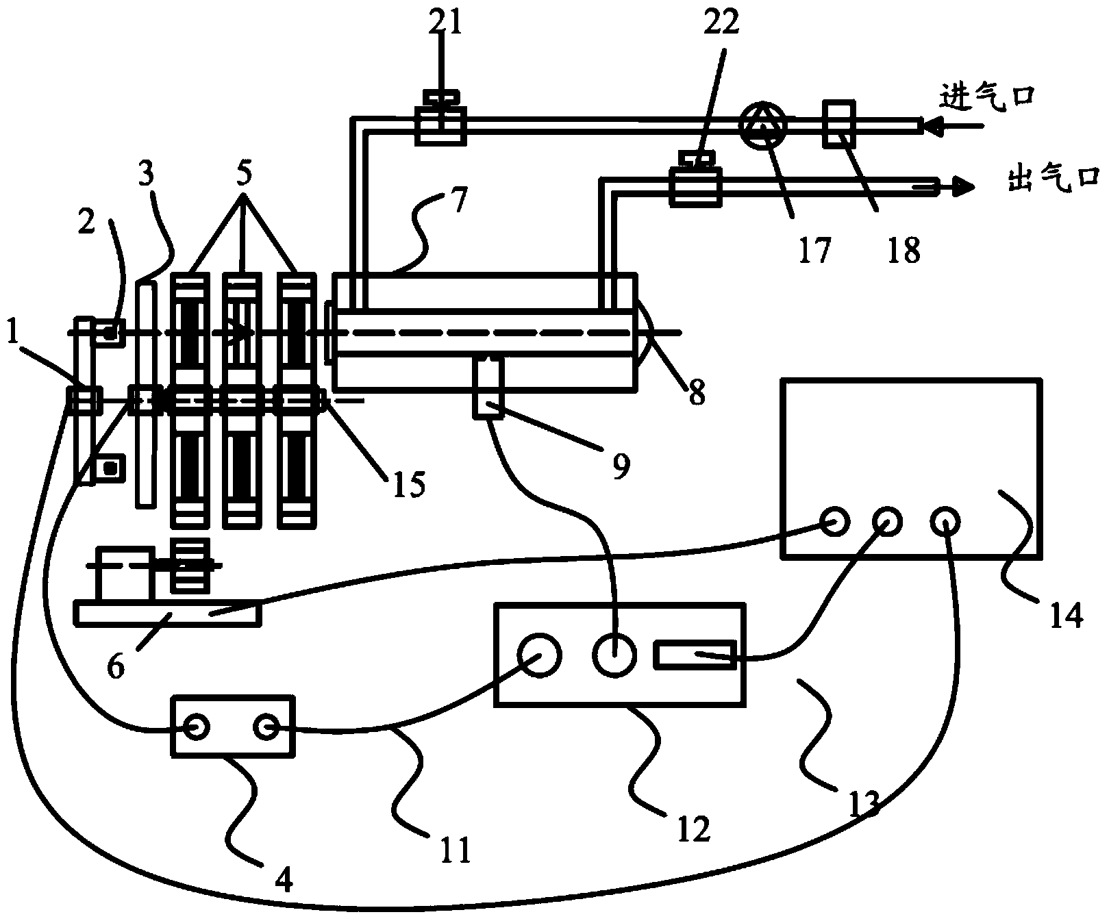
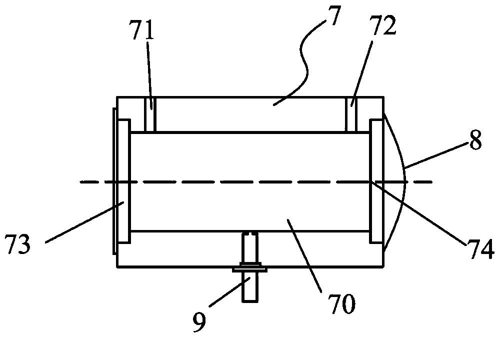
[0031] figure 2 It is a structural schematic diagram of a photoacoustic spectrum detection device with an axial multilayer optical filter disk structure of the present invention. like figure 2 As shown, the device of the present invention mainly includes a light source 2, a light source mounting bracket 1, a mechanical chopper 3, a chopper controller 4, a multilayer filter disk 5, a filter disk driver 6, a photoacoustic cell 7, and a light output Port parabolic reflector 8, high-sensitivity microphone 9, lock-in amplifier 12, embedded host 14, fixed shaft 15, circulating air pump 17, filter device 18, first solenoid valve 21, and second solenoid valve 22.

[0032] Measured gas from figure 2 The air inlet shown enters in, is driven by the circulating air pump 17 to flow along the pipeline, is filtered by the filter device 18, passes throug...


PUM

PropertyMeasurementUnit
diameteraaaaaaaaaa
lengthaaaaaaaaaa
Sensitivityaaaaaaaaaa

Abstract

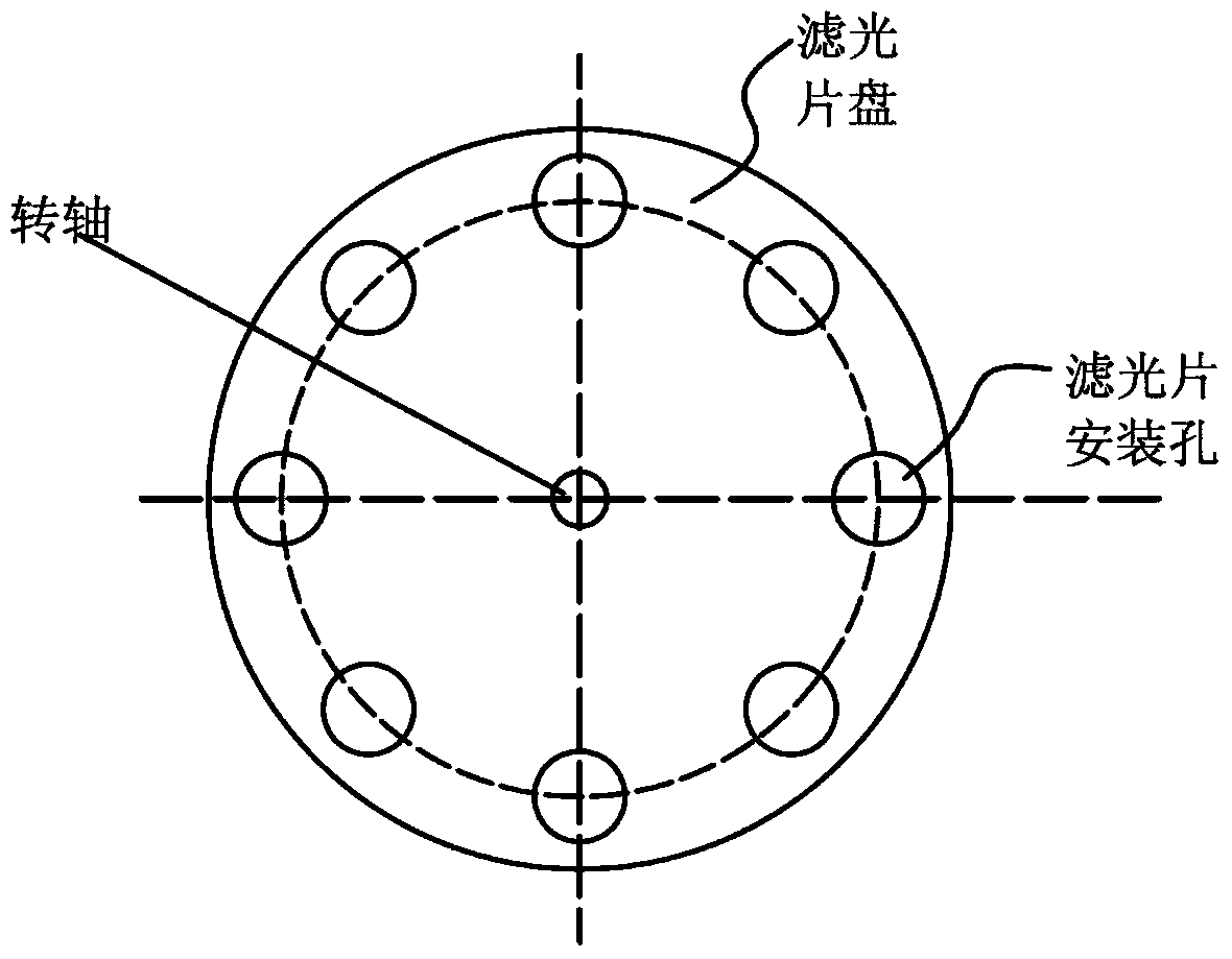
The invention relates to a photoacoustic spectrometry detection device adopting an axial multilayer filter plate structure. The photoacoustic spectrometry detection device adopting the axial multilayer filter plate structure comprises light sources, a light source installation support, a mechanical photochopper, a photochopper controller, multiple layers of filter plates, a filter plate drive device, a photoacoustic cell, a circulating air pump, a filter device, an electromagnetic valve, an light emitting opening parabolic reflector, a high-sensitivity microphone, a lock-phase amplifier and an embedded main machine. The photoacoustic spectrometry detection device is characterized in that the multiple layers of filter plates comprise two or more filter plates, each filter plate is of a gear-shaped structure, namely, the outer edge of each filter plate is provided with tooth grooves which are matched with a driving gear on the filter plate drive device. One of filter installation holes of each filter plate is not provided with a filter. Two or more filter plates are coaxially installed, and each filter plate is driven by the filter plate drive device to rotate. The filter plate drive device comprises a drive motor, a guide rail, a drive gear and an adjustable installation base. A plurality of filter plates can be driven by one filter plate drive device.

Description

technical field [0001] The invention relates to a gas detection device, in particular to a photoacoustic spectrum detection device capable of detecting various gases. Background technique [0002] Gas detection technology has a wide range of applications in industrial production and daily life, such as leak detection of oil and gas pipelines, detection of dissolved gases in transformer oil in power systems, detection of exhaust gases from chemical companies, and detection of trace pollutant gases in the air, Exhaled gas detection in human diseases and medical diagnosis, etc. [0003] For example, in the power industry, it is used to detect electrical equipment failures, such as power transformers, SF6, fluorocarbon mixed gas and other gas-insulated electrical equipment failure decomposition gas; [0004] For oil-filled power transformers, the characteristic gases that need to be detected are CH4, C2H4, H2, CO, CO2, C2H2, C2H6, etc. At present, there are many detection meth...

Claims


Application Information

Patent Timeline
Patent Type & Authority Applications(China)
IPC IPC(8): G01N21/01G01N21/3518
Inventor 张国强李康邱宗甲林涛
Owner INST OF ELECTRICAL ENG CHINESE ACAD OF SCI
Learn More