
Fitting structure of top lever device and shuttle changing device of computerized flat knitting machine

A technology of matching structure and flat knitting machine, applied in knitting, weft knitting, textiles and papermaking, etc., can solve problems such as missing stitches, fabric quality, grade influence, and experimental results can not reach the expected level, etc., to achieve The effect of accurate yarn feeding

Active Publication Date: 2014-12-24
JIANGSU JINLONG TECHNOLOGY CO LTD
View PDF7 Cites 5 Cited by
  • Summary
  • Abstract
  • Description
  • Claims
  • Application Information

AI Technical Summary

Problems solved by technology

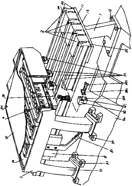
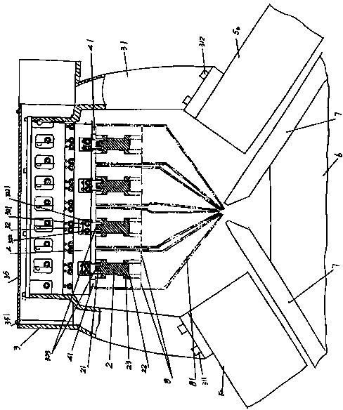
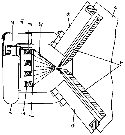
[0005] The above-mentioned structure has the following technical problems in the actual working process: because the lengthy shuttle guide rail 2 corresponds to the above between the aforementioned pair of needle plates 7 in an empty state, and because the middle part of the head connecting seat 3 and the shuttle guide rail 2 Keep a vacant distance between them, that is, the middle part of the head connecting seat 3 corresponds to the top of a group of shuttle guide rails 2 in a vacant state, so during the yarn feeding process when the shuttle 8 reciprocates along the shuttle guide rail 2, the shuttle guide rail 2 will produce Unavoidable trembling (that is, trembling) phenomenon, especially when the length of a pair of needle plates 7 is longer and the knitting speed is higher, because the length of the shuttle guide rail 2 is correspondingly long, so the shaking and shaking of the shuttle guide rail 2 become more and more serious. Seriously, the shaking and shaking of the shuttle guide rail 2 will be passed on to the shuttle 8, that is to say, when the shuttle 8 moves on the shaking and shaking shuttle guide rail 2, it is difficult to obtain an accurate yarn feeding effect for the knitting mechanism, and when the feeding of the shuttle 8 When the yarn feeder 81 is inaccurate in feeding the yarn to the knitting mechanism, it is easy to cause missing stitches, so that the fabric woven by the knitting mechanism is defective, and the quality and grade of the fabric are affected.
[0006] The way to solve the above-mentioned technical problem at present is: between each two adjacent shuttle guide rails 2 in a group of shuttle guide rails 2 and be respectively provided with spacer at both ends, this can be provided by Chinese invention patent application publication number CN103806208A " A computerized horizontal knitting machine skybar positioning device "confirms, but the experiment proves that the effect cannot reach the desired level, because the vibration situation in the middle area of ​​the length direction of the shuttle guide rail 2 cannot be eliminated, and because the head connecting seat 3 Overhang problem with shuttle guide 2 still exists

Method used


Image

  • Fitting structure of top lever device and shuttle changing device of computerized flat knitting machine
  • Fitting structure of top lever device and shuttle changing device of computerized flat knitting machine
  • Fitting structure of top lever device and shuttle changing device of computerized flat knitting machine

Examples


Embodiment Construction

[0022] In order to enable the examiners of the patent office, especially the public, to understand the technical essence and beneficial effects of the present invention more clearly, the applicant will describe in detail the following in the form of examples, but none of the descriptions to the examples is an explanation of the solutions of the present invention. Any equivalent transformation made according to the concept of the present invention which is merely formal but not substantive shall be regarded as the scope of the technical solution of the present invention.

[0023] See figure 1 and figure 2 , a pair of shuttle guide rails 1 and a set of shuttle guide rails 2 belonging to the structural system of the sky bar device are given. The two ends of the top of the frame 6 of the computerized flat knitting machine, specifically: a pair of shuttle guide rail frames 1 has a shuttle rail frame fixed on one end of the top of the frame 6, and a pair of shuttle rail frames 1 ...


PUM


Abstract

The invention provides a fitting structure of a top lever device and a shuttle changing device of a computerized flat knitting machine, and belongs to the technical field of computerized flat knitting machines. The top lever device comprises a pair of shutter guide rail brackets and a group of shuttle guide rails; the shuttle changing device comprises a nose connecting base and a group of shuttle changing control electromagnetic valves; the fitting structure of the top lever device and the shuttle changing device is characterized in that shuttle guide rail attached guide bars are arranged on the surfaces of the upward sides of the group of shuttle guide rails in the length direction respectively, shuttle guide rail limiting sliders are fixed on the front and rear sides of the nose connecting base respectively, and the shuttle guide rail limiting sliders are in sliding fit with the shuttle guide rail attached guide bars. In the process when the shuttle changing control electromagnetic valves moving along with the nose connecting base drive shuttles to move back and forth along the shuttle guide rails, the shuttle guide rails do not, for example, vibrate and shake, so as to ensure that the shuttles driven by the shuttle changing control electromagnetic valves move steadily on the shuttle guide rails and yarns can be accurately fed into a knitting mechanism by the shuttles; therefore, the situation that the quality of the fabrics are finally affected by missed stitch due to inaccurate yarn feeding can be avoided.

Description

technical field [0001] The invention belongs to the technical field of computerized flat knitting machines, and in particular relates to a matching structure of a sky bar device and a shuttle changing device of a computerized flat knitting machine. Background technique [0002] The aforesaid sky bar device is usually referred to as "sky bar" or "shuttle guide rail" for short by the industry. For this, please refer to the "positioning reference device for the installation of the shuttle guide rail of computerized flat knitting machine" recommended by Chinese patent application publication number CN103422248A Paragraph 0018 of the instructions. [0003] The matching structure of the sky bar device and the shuttle changing device of the computer knitting flat knitting machine in the prior art including the aforementioned CN103422248A is composed of image 3 As shown, the sky bar device includes a pair of shuttle guide rails 1 and a set of shuttle guide rails 2, and a pair of s...

Claims


Application Information

Patent Timeline
Patent Type & Authority Applications(China)
IPC IPC(8): D04B15/70D04B15/10
Inventor 金永良兰先川海港付洪平孙健徐备松
Owner JIANGSU JINLONG TECHNOLOGY CO LTD
Learn More