Hot core box core shooter
A technology of a hot core box and a core shooter, which is applied in the field of core shooters, can solve the problems of high production cost and high energy consumption, and achieve the effects of high action efficiency, high degree of automation and less energy.
- Summary
- Abstract
- Description
- Claims
- Application Information
AI Technical Summary
Problems solved by technology
Method used
Image
Examples
Embodiment 1
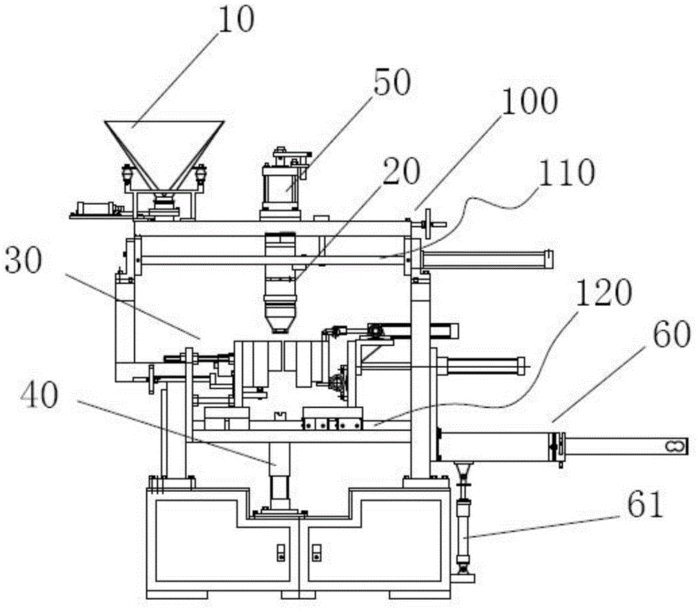
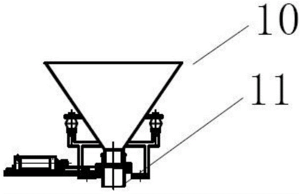
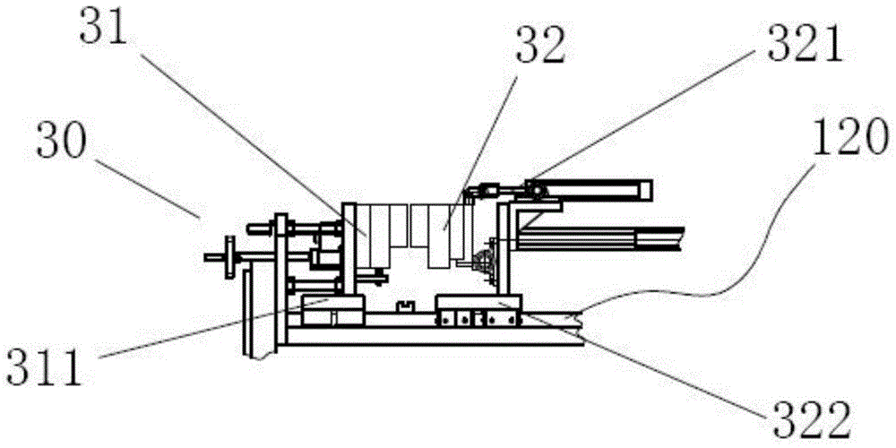
[0044] see Figure 1-3, the present embodiment discloses a hot box core shooter, including a frame 100 as an installation base, a shakeout mechanism 10 is provided on the top of the frame 100, and the shakeout mechanism 10 is used to store sand materials, and remove the sand materials from The sand-out port 11 on it is transported to the sand-shooting cylinder 20, and the tail of the sand-shooting tube 20 can correspond to the sand-out port 11. After the sand material enters the sand-shooting tube 20, there can be high pressure in the sand-shooting tube 20. The gas is pushed and injected, and the frame 100 is also provided with a mold clamping mechanism 30 for clamping the hot core box mold, and a core pulling mechanism for fixing the formed sand core is provided under the mold clamping mechanism 30 40. The sand shooting port 21 of the sand shooting cylinder 20 can move back and forth up and down, so as to extend into or out of the mold cavity of the hot core box mold.
[004...
Embodiment 2
[0062] This embodiment is a deformation on the basis of Embodiment 1. The difference between this embodiment and Embodiment 1 is that, as another setting method of the sand shooting cylinder 20, the guide device also includes a The first guide rail 110 on the top, the first guide rail 110 passes through the outer sleeve 22, so that the sand shooting cylinder 20 can slide back and forth along the first guide rail 110 between the sand shakeout mechanism 10 and the mold clamping mechanism 30 between.
Embodiment 3
[0064] This embodiment is a modification on the basis of Embodiments 1 and 2. In this embodiment, the guide device further includes a first guide rail 110 arranged on the frame 100, and the first guide rail passes through the The outer sleeve 22 enables the sand shooting cylinder 20 to slide back and forth along the first guide rail 110 between the shakeout mechanism 10 and the mold clamping mechanism 30, and also includes the sand shooting cylinder 20 moving along the first guide rail 110. A guide rail (110) slides back and forth between the guide part 22 between the sand shakeout mechanism 10 and the mold clamping mechanism 30, and the setting of the guide part 22 combines with the first guide rail 110 passing through the outer sleeve 22 so that the present embodiment The sand shooting cylinder 20 can move on the first guide rail 110 more stably, so that the phenomenon of lateral deviation is less likely to occur.
PUM
 Abstract
Description
Claims
Application Information
 - R&D
- Intellectual Property
- Life Sciences
- Materials
- Tech Scout
- Unparalleled Data Quality
- Higher Quality Content
- 60% Fewer Hallucinations
Browse by: Latest US Patents, China's latest patents, Technical Efficacy Thesaurus, Application Domain, Technology Topic, Popular Technical Reports.
© 2025 PatSnap. All rights reserved.Legal|Privacy policy|Modern Slavery Act Transparency Statement|Sitemap|About US| Contact US: help@patsnap.com


