
Heat sink

A heat sink and heat sink technology, applied in heat exchange equipment, lighting and heating equipment, cooling/heating devices of lighting devices, etc., can solve the problem of high difficulty in controlling the thickness precision of heat sinks, different production molds for heat sinks, and LED heat dissipation Eliminate problems such as device scrapping, achieve the effects of reducing weight and consumables, high assembly efficiency, and reducing the difficulty of production and processing

Inactive Publication Date: 2014-12-17
杨小晨
View PDF0 Cites 4 Cited by
  • Summary
  • Abstract
  • Description
  • Claims
  • Application Information

AI Technical Summary

Problems solved by technology

For the problem of heat dissipation, fans are generally used in the prior art to actively dissipate heat, or heat sinks are used to passively dissipate heat. However, the disadvantages of using fans to actively dissipate heat are: the fan has noise and dust accumulation, and the service life cannot be guaranteed.
[0004] 1. During the production of the radiator, it is difficult to control the precision of the thickness of the radiator;
[0005] 2. If there is a defect in a certain part of the radiator, the entire LED radiator will be scrapped, which will easily cause a lot of waste and also lead to a decrease in production efficiency;
[0006] 3. The whole set of production molds for radiators of different specifications are different, and the versatility is not strong

Method used


Image

  • Heat sink
  • Heat sink
  • Heat sink

Examples


Embodiment Construction

[0034] It should be understood that the specific embodiments described here are only used to explain the present invention, not to limit the present invention.

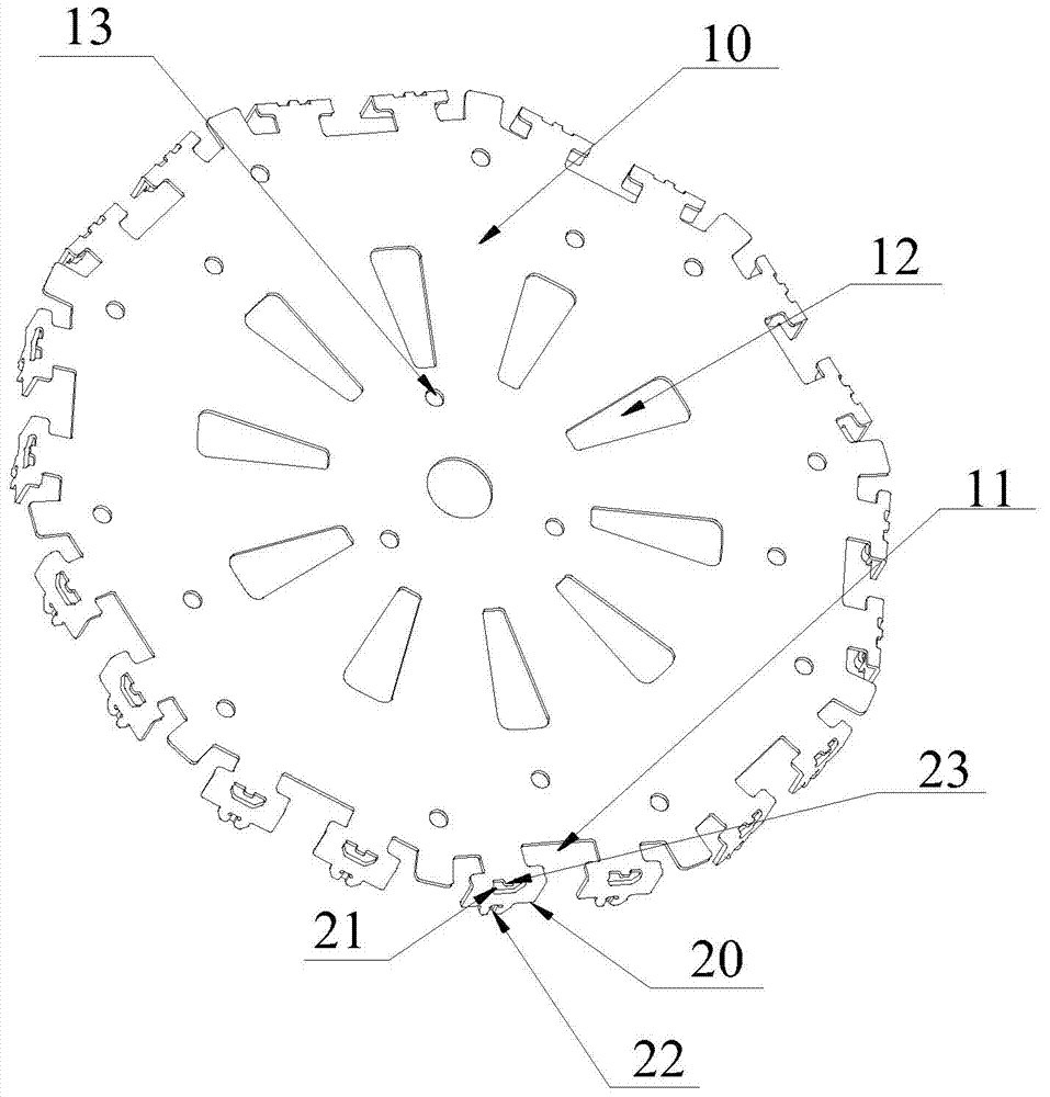
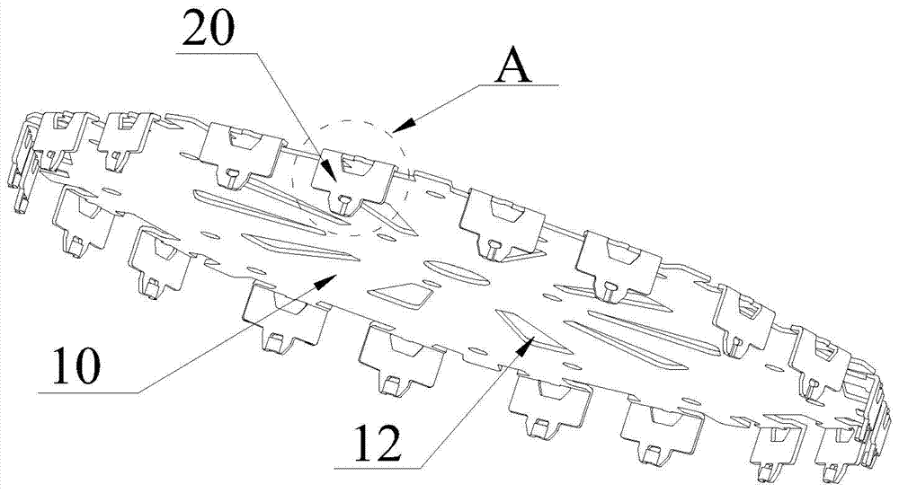
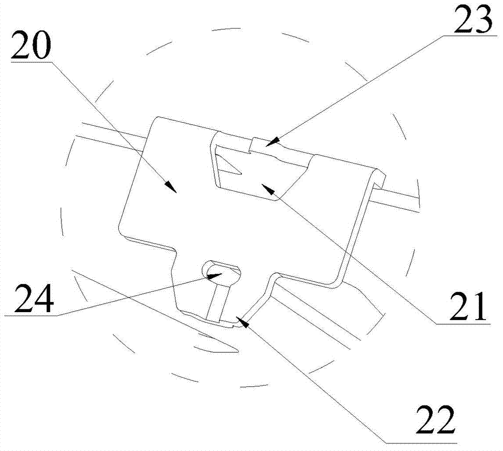
[0035] refer to Figure 1 to Figure 7 , an embodiment of the heat sink of the present invention is proposed, the heat sink is columnar, and is formed by stacking and assembling a plurality of heat sinks 10 produced separately. The heat sink 10 is arranged in a regular polygon, and several connecting fins 20 are vertically arranged on the edge of the heat sink 10. The positions of the connecting fins 20 on the laminated heat sinks 10 are aligned, and the connecting fins 20 are used for the connection between the laminated heat sinks 10. . The connecting sheet 20 is formed by extending vertically downward along the edge of the heat sink 10 , and integrally formed with the heat sink 10 . A notch 21 with an open upper end is provided on the upper part of the connecting piece 20 . The notch 21 is formed by cutting downwa...


PUM


Abstract

The invention discloses a heat sink. The heat sink is formed by stacking and assembling a plurality of cooling fins, the production process of one single cooling fin is simple, the production machining difficulty of the heat sink can be reduced, and the production efficiency is improved; a plurality of connecting pieces are perpendicularly arranged on the edge of each cooling fin, groove openings with openings in the upper ends are formed in the upper portions of the connecting pieces, inserting pieces matched with the groove openings are arranged on the lower portions of the connecting pieces, tenons which protrude outwards are arranged on the upper end sides of the groove openings, and mortises matched with the tenons are arranged on the inserting pieces; the cooling fins are placed in a stacking mode, the positions of the connecting pieces on the adjacent cooling fins are aligned with one another in a one-to-one mode, when the cooling fins are assembled, inserting pieces on the upper layer connecting pieces are inserted into inserting openings in the lower layer connecting pieces, meanwhile, the tenons on the inserting openings are buckled into the mortises on the inserting pieces, the adjacent cooling fins are connected, the assembling and operation are easy, and can be rapidly completed, and the assembling efficiency is high. After assembly, the opposite faces of the adjacent cooling fins are distanced by gaps, ventilation and heat dissipation are facilitated, each cooling fin can be in full contact with air, and the heat dissipation efficiency is improved.

Description

technical field [0001] The invention relates to the technical field of LED lighting, in particular to a radiator with fast heat dissipation. Background technique [0002] The problem of heat dissipation is an important problem that needs to be solved for many power electronic equipment, LED lamps and other heat-prone devices. The quality of the heat dissipation effect is directly related to the service life of the device. For the problem of heat dissipation, fans are generally used in the prior art to actively dissipate heat, or radiators are used to passively dissipate heat. However, the disadvantages of using fans to actively dissipate heat are: the fans are noisy and dusty, and the service life cannot be guaranteed. When a radiator is used for passive heat dissipation, a radiator with a larger heat dissipation volume is required to satisfy heat dissipation. [0003] Existing radiators have different shapes, and most of them are equipped with cooling fins. The radiators w...

Claims


Application Information

Patent Timeline
Patent Type & Authority Applications(China)
IPC IPC(8): F21V29/00F28F3/08F21Y101/02
Inventor 杨小晨
Owner 杨小晨
Learn More