LED lighting lamp

A technology for LED lighting and LED modules, applied in lighting devices, lighting and heating equipment, cooling/heating devices for lighting devices, etc. Reduced capital investment, enhanced heat dissipation capability, and the effect of small radiators

Inactive Publication Date: 2014-12-17
上海汇生光电科技有限公司
View PDF0 Cites 2 Cited by
  • Summary
  • Abstract
  • Description
  • Claims
  • Application Information

AI Technical Summary

Problems solved by technology

[0003] At present, LEDs are all driven by DC, so a constant current drive power supply needs to be added between the mains and the LED to convert the AC mains into a suitable DC for LEDs. Due to the existence of this constant current drive power, LED lamps must provide a place The drive cavity of the constant current drive power supply, so the radiator of the LED lamp must be a hollow columnar body, and due to the standard restrictions on the shell and appearance of the lamp, the radiators of the current LED lamps are relatively large and heavy, resulting in the entire lamp. The traditional lamps will be much heavier, and the installation reliability and safety will be seriously affected; and the light-emitting surface of the lamps will be smaller than the traditional lamps, which limits the popularity and application of LED lamps
In addition, because there are a large number of electrolytic capacitors and magnetic components in this constant current drive power supply to improve harmonics and electromagnetic compatibility problems, it often leads to shorter life of the entire LED lamp and poor electromagnetic compatibility.
Moreover, the constant current drive power supply is generally placed in the drive cavity, and the heating device cannot be in direct contact with the radiator, resulting in poor heat dissipation capability of the constant current drive power supply, which indirectly deteriorates the reliability of the lamp, shortens the life, and deteriorates the efficiency.

Method used


Image

  • LED lighting lamp
  • LED lighting lamp
  • LED lighting lamp

Examples


Embodiment Construction

[0024] The invention realizes the 9W G60 non-magnetic component, no electrolysis, drive integrated light-emitting board, small heat sink, high PF, low harmonic, high-life dimmable LED wide-light bulb lamp scheme.

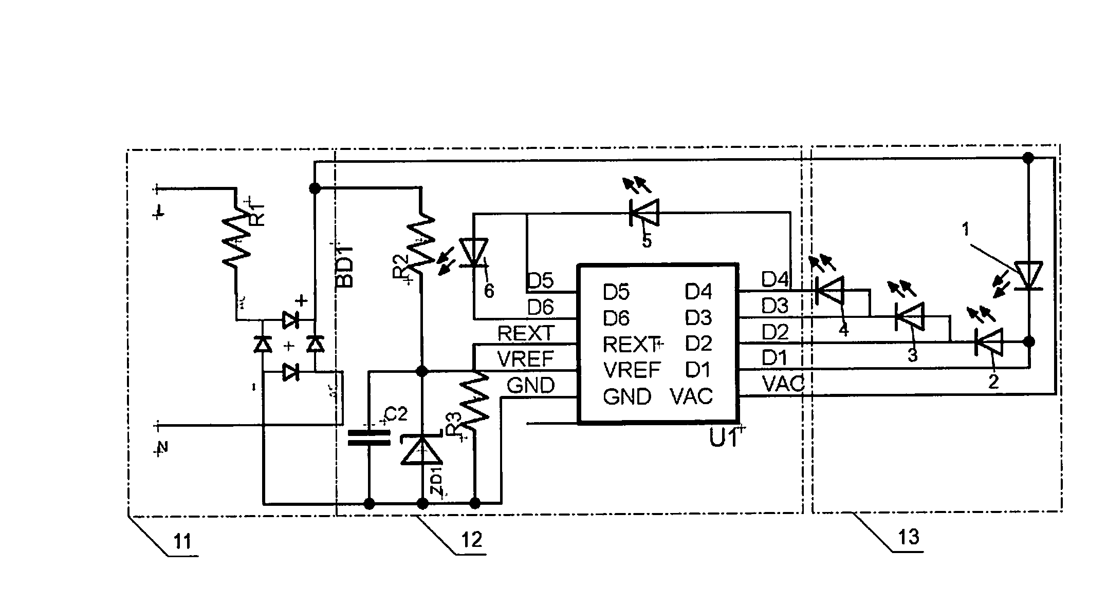
[0025] Such as figure 1 As shown, the LED lighting fixture of the present invention includes an AC-DC rectification circuit 11, a constant current control circuit 12 and an LED module group 13; the AC-DC rectification circuit 11 includes an AC input terminal AC_L&AC_N, a protection overcurrent device R1, a full-bridge rectifier circuit BD1 that converts the input power frequency alternating current into pulsating direct current; the constant current control loop 12 includes a subsection start control circuit, a pulse constant current control circuit U1 and a constant current The limiting circuit, the subsection start control circuit is composed of the second resistor R2, the Zener diode ZD1, and the second capacitor C2, and the constant current limiting circuit is c...


PUM


Abstract

The invention discloses an LED lighting lamp which comprises an AC-DC rectification circuit, a constant current control circuit and an LED module group. The AC-DC rectification circuit comprises an alternating-current input end, a device for protecting overcurrent and a full-bridge rectification circuit which are connected in sequence. The full-bridge rectification circuit converts input power frequency alternating current into pulsating direct current. The constant current control circuit comprises a segmented starting control circuit, a pulse constant current control circuit and a constant current limiting circuit which are connected in sequence. The sub-stage starting control circuit comprises a second resistor, a voltage-stabilizing diode and a second capacitor. The constant current limiting circuit comprises a third resistor. The LED module group comprises six LED modules. High-voltage LEDs or COB-packaged LEDs or self-establishing LED groups are used in the LED module group. Input alternating current is converted into frequency-doubled pulsating direct current which is converted into segmented direct current constant current to be output.

Description

technical field [0001] The invention relates to a lamp, in particular to an LED lighting lamp. Background technique [0002] LED (Lighting Emitting Diode) is a light-emitting diode, which is a semiconductor solid-state light-emitting device. It uses a solid semiconductor chip as a light-emitting material, and the excess energy is released through the recombination of carriers in the semiconductor to cause photon emission and directly emit light. LED lighting products are lighting appliances manufactured using LEDs as light sources. LED is called the fourth-generation lighting source or green light source. It has the characteristics of energy saving, environmental protection, long life, and small size. It can be widely used in various indications, displays, decorations, backlights, general lighting and urban night scenes. The LED light source is driven by DC, and the electro-optic power conversion is close to 100% with ultra-low power consumption (0.03 watts to 1 watt for a...

Claims


Application Information

Patent Timeline
Patent Type & Authority Applications(China)
IPC IPC(8): F21V29/00H05B37/00F21Y101/02
CPCY02B20/40
Inventor 沈春辉耿明
Owner 上海汇生光电科技有限公司
Why Eureka
Try Eureka