Refining method of argon gas and refining device

A refining method and refining device technology, which are applied in separation methods, chemical instruments and methods, inert gas compounds, etc., can solve the problems of reduced argon recovery rate, pressure rise, increased argon gas obstruction, etc., and improved argon gas recovery rate. , The effect of eliminating pressure fluctuation and improving the effect of decompression and regeneration

Active Publication Date: 2014-12-17
SUMITOMO SEIKA CHEM CO LTD
View PDF5 Cites 2 Cited by
  • Summary
  • Abstract
  • Description
  • Claims
  • Application Information

AI Technical Summary

Problems solved by technology

However, in the prior art described above, since the gas pipeline through which the exhaust gas flows is fixed, the flow resistance of the gas increases due to the increase in the amount of gas from the adsorption tower, and the pressure of the space where the exhaust gas flows temporarily rises during the desorption operation.
The pressure increase caused by the fluctuation of the exhaust gas amount will reduce the desorption regeneration effect of the adsorbent, and become an obstacle to the improvement of the recovery rate or purity of argon gas. However, in the above-mentioned prior art, the fluctuation caused by the exhaust gas amount is not considered Effects of reduced recovery or reduced purity of argon

Method used


Image

  • Refining method of argon gas and refining device
  • Refining method of argon gas and refining device
  • Refining method of argon gas and refining device

Examples


Embodiment 1

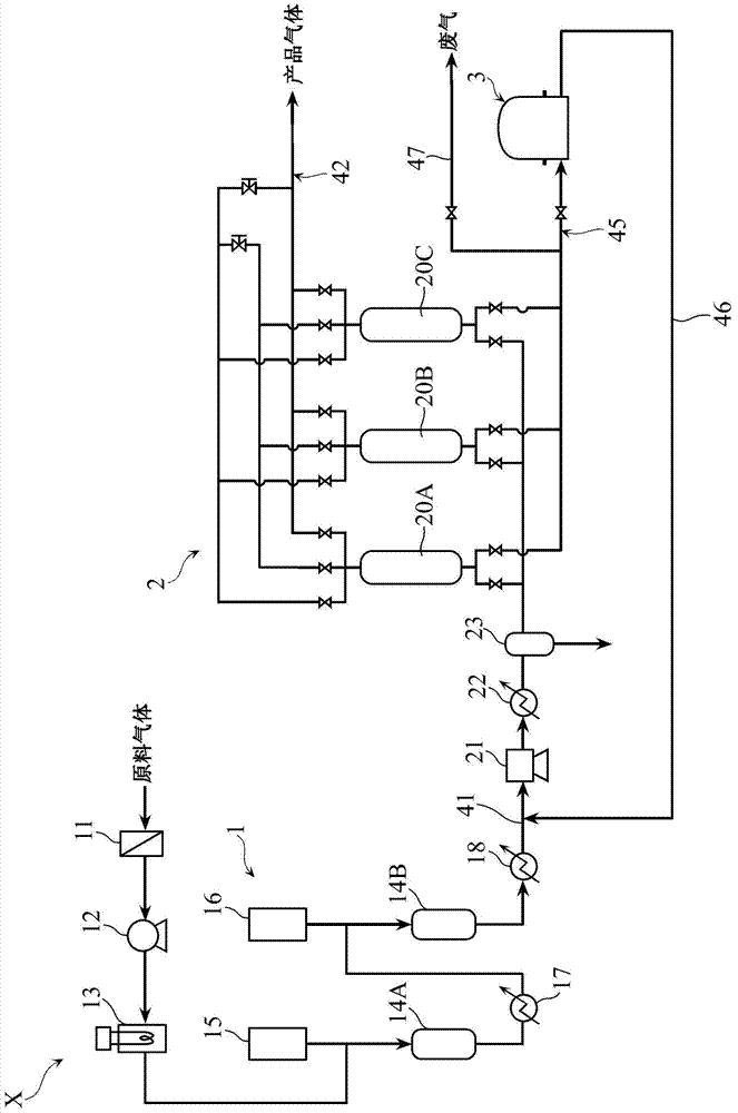
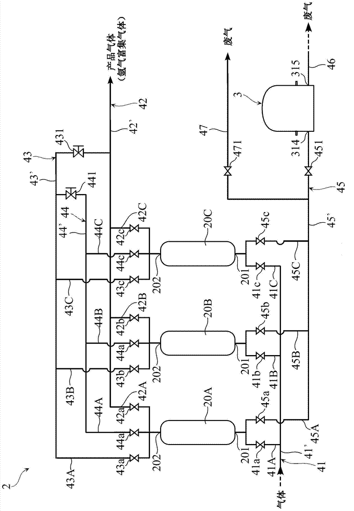
[0164] By using the figure 1 , figure 2 The argon refining device X of the schematic structure shown, and repeat in adsorption tower 20A, 20B, 20C by Figure 4 , Figure 5 The shown adsorption process, downstream decompression process, equal pressure (decompression) process, countercurrent decompression process, cleaning (first cleaning) process, cleaning (second cleaning) process, equal pressure (boosting) process and boost One cycle (steps 1 to 12) consisting of pressing process, concentrates and purifies argon from the specified mixed gas.

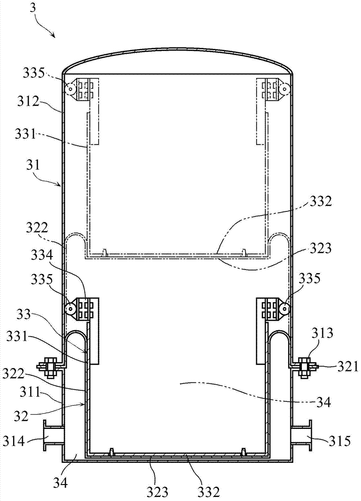
[0165] The adsorption towers 20A, 20B, and 20C used in this example are all made of stainless steel, have a cylindrical shape (with an inner diameter of 37 mm, and an inner dimension height of 1000 mm), and have a capacity of about 1 dm 3 . Each adsorption tower is filled with 1dm 3 LiX-type zeolites were used as adsorbents. Regarding the gas holder, use Figure 7 The shown ball type (capacity variable) accumulator 3A has a capa...

Embodiment 2

[0168] In the present embodiment, the operating conditions of the PSA device and the PSA method are the same as in Example 1, but the waste gas derived from the adsorption towers 20A, 20B, and 20C in the cleaning (second cleaning) process is discharged outside the system, and the remaining waste gas { In the cleaning (first cleaning) process (steps 1, 5, 9) and the countercurrent decompression process (steps 4, 8, 12), the exhaust gases derived from the adsorption towers 20A, 20B, and 20C are all added to the adsorption tower 20A. , 20B, 20C before the pre-treatment of the mixed gas, recirculation. The gas volume of the recirculation gas at this time is 145Ndm 3 / h, the composition of the recycle gas is 98.47 mol % of argon, 0.05 mol % of carbon monoxide, 1.02 mol % of carbon dioxide, and 0.47 mol % of nitrogen. The mixed gas with recirculation gas will be added (new pre-treated gas 885Ndm 3 / h and recycle gas 145Ndm 3 / h) at 1030Ndm3 The flow rate of / h is continuously supp...


PUM


Abstract

The invention provides a refining method of argon gas and a refining device requiring high purity argon gas with high yield rate. In argon gas refining operation in a pressure swing adsorption way, even when waste gas quantity varies, pressure of the gas can be lowered as possible. The pressure swing adsorption method is processed via an absorption tower (20A-20C) filled with absorption agent and a circulation containing absorption procedure and an adverse current pressure-reduction procedure; in the absorption procedure, the absorption tower is at a high pressure state and when mixed gas is introduced into the absorption tower, impurities in the mixed gas can be absorbed on the absorption agent, so gas enriched with argon gas can be lead out via the absorption tower; in the adverse current pressure-reduction procedure, the absorption tower is pressure-reduced, so impurities can be desorbed from the absorption agent and gas can be led out of the absorption tower; with the above method, gas led our of the absorption tower in the adverse current pressure-reduction procedure can be introduced into a gas storer (3) with various capacity; and the pressure of the gas storer (3) can be fixed and gas in the storer (3) can be discharged.

Description

technical field [0001] The present invention relates to a method and a device for refining argon by pressure swing adsorption. Background technique [0002] Argon obtained from the air by a cryogenic separation device is used as the atmosphere gas in a single crystal silicon crystal pulling furnace, a ceramic sintering furnace, a vacuum degassing furnace for steelmaking, a silicon plasma melting furnace for solar cells, and a polysilicon casting furnace. gas. Because only 0.9% of argon exists in the air, its manufacturing cost is several times higher than that of oxygen and nitrogen. Therefore, it is effective to temporarily recover and reuse the argon gas used as the atmosphere gas, but the argon gas used as the atmosphere gas in the furnace is mixed with impurities such as carbon monoxide, carbon dioxide, hydrogen, and air, and its purity is lowered. Therefore, in order to improve the purity of the recovered argon, and to realize the reuse in the furnace, the following t...

Claims


Application Information

Patent Timeline
IPC IPC(8): C01B23/00B01D53/053
CPCB01D53/047B01D2253/108C01B23/0052C01B2210/0014C01B2210/0034
Inventor 岸井充春名一生志摩康一
Owner SUMITOMO SEIKA CHEM CO LTD
Why Eureka
Try Eureka