Method and device for electrodynamically braking a universal motor

A technology of electrodynamics and braking devices, applied in the direction of motor generator control, AC motor control, electrical components, etc., can solve the problems of armature wear, failure, unsuitable speed change, etc., and achieve the effect of reducing wear

Active Publication Date: 2017-10-13
ROBERT BOSCH GMBH
View PDF1 Cites 0 Cited by
  • Summary
  • Abstract
  • Description
  • Claims
  • Application Information

AI Technical Summary

Problems solved by technology

The disadvantage is that the method disclosed here is not suitable for speed changes during braking operation due to external influences or changes in the nominal speed
This can lead to serious failures such as undesired restarting of the universal motor and / or increased brush sparking which can lead to wear on the armature of the universal motor

Method used


Image

  • Method and device for electrodynamically braking a universal motor
  • Method and device for electrodynamically braking a universal motor
  • Method and device for electrodynamically braking a universal motor

Examples


Embodiment Construction

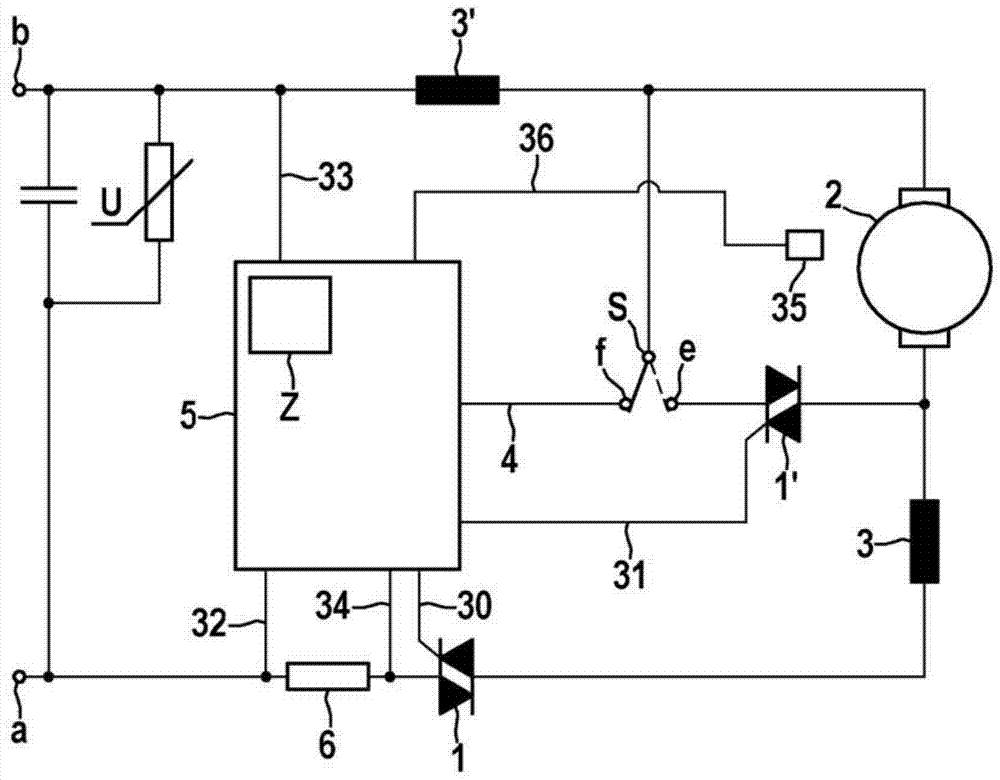
[0022] figure 1 A schematic circuit diagram of an electrodynamic braking device for an electric universal motor is shown. The device corresponds substantially to the assembly disclosed in WO2011 / 076827. The electrodynamic braking device has a command assignment Z within the electronic control unit 5 (which can be designed, for example, as a microcontroller circuit). Here, the assignment Z includes the firing angle of the second electronic semiconductor switch 1' A plurality of combinations of respective rotational speeds of the universal motor which result from the previously ascertained ideal braking operation of the universal motor. The rotational speed sensor 35 is provided for continuously ascertaining the rotational speed of the universal motor during braking operation. about figure 1 Further circuit and functional details of the components shown in are not described in depth as they are already known from WO 2011 / 076827.

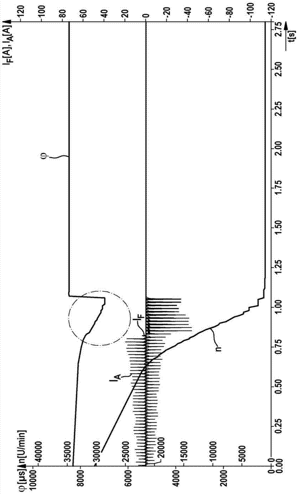
[0023] figure 2 shows a schematic time p...


PUM


Abstract

The invention proposes an improved electrodynamic method for braking a universal motor. The actual rotational speed is adapted by means of the assignment of the ignition angle of the electronic semiconductor switch which short-circuits the armature of the universal motor during the braking process to the rotational speed, by ascertaining the rotational speed of the ignition angle of said semiconductor switch. This advantageously results in significantly shorter braking times and significantly reduced brush sparking at the armature, which advantageously reduces wear and thus provides the universal motor with an increased service life.

Description

technical field [0001] The present invention relates to a method and a device for electrodynamically braking a universal motor. Background technique [0002] A method for electrodynamically braking a universal motor is known, for example, from WO 2011 / 076827. A disadvantage is that the method disclosed here is not suitable for rotational speed changes during braking operation due to external influences or changes in the setpoint rotational speed. This can lead to serious malfunctions, such as undesired restarting of the universal motor and / or increased brush sparking which can lead to wear on the armature of the universal motor. Contents of the invention [0003] It is therefore the object of the present invention to propose an improved method for electrodynamically braking a universal motor. [0004] According to a first aspect, the object is solved by a method for electrodynamically braking a universal motor, which has the following steps during braking operation: [...

Claims


Application Information

Patent Timeline
Patent Type & Authority Patents(China)
IPC IPC(8): H02P3/18H02P25/14
CPCH02P3/18H02P25/14
Inventor J·维什涅夫斯基K·波戈热尔斯基
Owner ROBERT BOSCH GMBH
Why Eureka
Try Eureka