Exhaust purification device of internal combustion engine

一种排气净化装置、内燃机的技术,应用在排气装置、排气处理装置的电控、内燃活塞发动机等方向,能够解决燃料消耗量增大等问题

Inactive Publication Date: 2014-12-10
TOYOTA JIDOSHA KK
View PDF5 Cites 0 Cited by
  • Summary
  • Abstract
  • Description
  • Claims
  • Application Information

AI Technical Summary

Problems solved by technology

[0005] However, if the operation mode is switched to the stoichiometric air-fuel ratio operation mode in this way and combustion is performed on the basis of the stoichiometric air-fuel ratio, there is a problem of increased fuel consumption.

Method used


Image

  • Exhaust purification device of internal combustion engine
  • Exhaust purification device of internal combustion engine
  • Exhaust purification device of internal combustion engine

Examples


Embodiment Construction

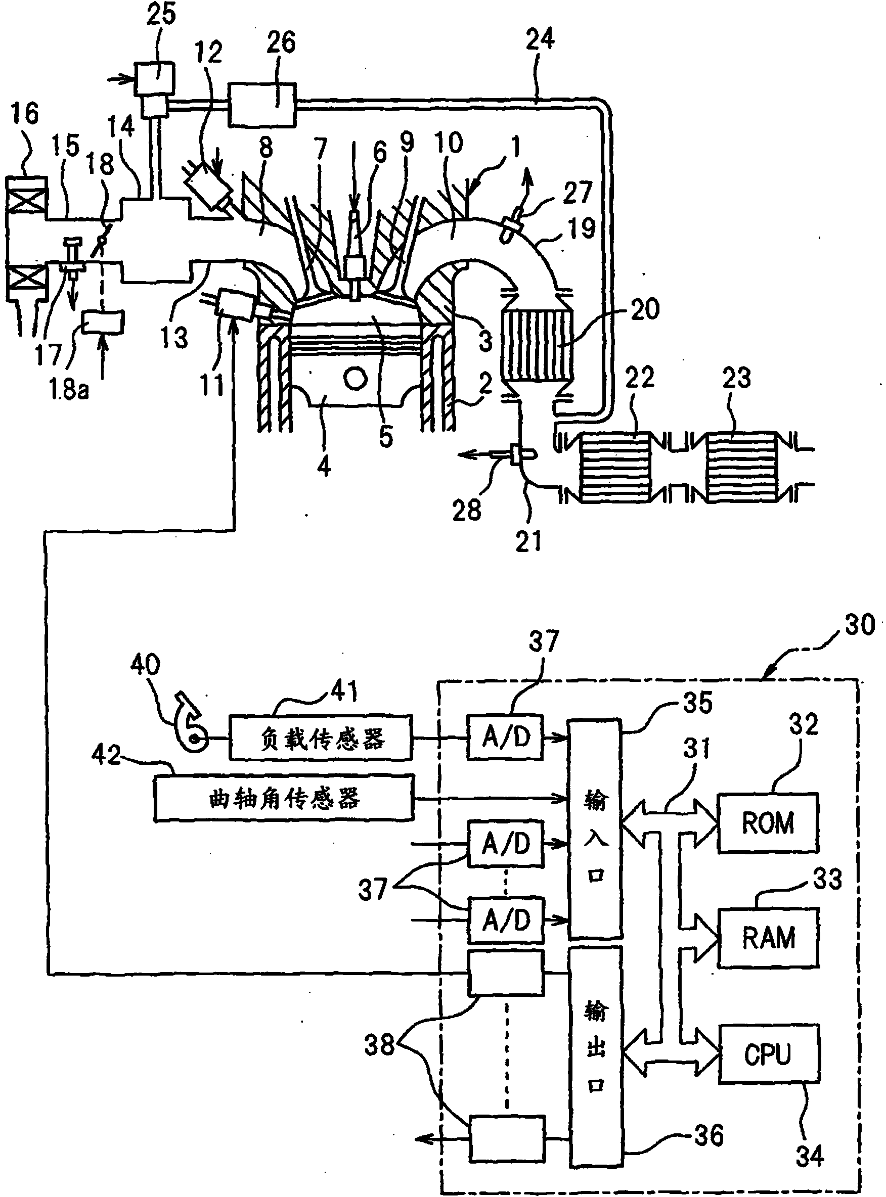
[0030] figure 1 An overall view showing a spark ignition internal combustion engine.

[0031] refer to figure 1 It can be seen that 1 represents the main body of the internal combustion engine, 2 represents the cylinder block, 3 represents the cylinder head, 4 represents the piston, 5 represents the combustion chamber, 6 represents the ignition plug, 7 represents the intake valve, 8 represents the intake port, 9 represents the exhaust valve, and 10 represents the exhaust valve. Indicates the exhaust port. Such as figure 1 As shown, each cylinder has a pair of fuel injection valves consisting of an electronically controlled fuel injection valve 11 for injecting fuel into the combustion chamber 2 and an electronically controlled fuel injection valve 12 for injecting fuel into the intake port 8. . The intake port 8 of each cylinder is connected to a surge tank 14 via an intake branch pipe 13 , and the surge tank 14 is connected to an air filter 16 via an intake duct 15 . An ...


PUM


Abstract

A three way catalyst (20) and an NO x storage catalyst (22) are arranged in an engine exhaust passage. In an engine low load operating region, a combustion is performed under a lean air-fuel ratio, and when NO x should be released from the NO x storage catalyst (22), the air-fuel ratio in a combustion chamber (5) is made rich. In an engine medium load operating region, the base air-fuel ratio is made lower as compared with the engine low load operating region, and the air-fuel ratio in the combustion chamber (5) is made rich at a shorter period as compared with the engine low load operating region. When the operating state of the engine is switched from the engine low load operating region to the engine medium load operating region, the air-fuel ratio in the combustion chamber (5) is temporarily made rich, and the degree of richness of the air-fuel ratio at this time is stepwise lowered.

Description

technical field [0001] The present invention relates to an exhaust purification device for an internal combustion engine. Background technique [0002] There is known an internal combustion engine in which a three-way catalyst is arranged in the exhaust passage of the internal combustion engine, and in the exhaust passage of the internal combustion engine downstream of the three-way catalyst, the NO in the exhaust gas is stored when the air-fuel ratio of the inflowing exhaust gas is a lean air-fuel ratio. X , if the air-fuel ratio of the inflowing exhaust gas is a rich air-fuel ratio, the stored NO will be released X NO X According to the operating state of the internal combustion engine, the operation mode of the internal combustion engine is switched between a lean air-fuel ratio operation mode in which combustion is performed on the basis of a lean air-fuel ratio, and a theoretical air-fuel ratio operation mode in which combustion is performed on the basis of a theoretic...

Claims


Application Information

Patent Timeline
Patent Type & Authority Applications(China)
IPC IPC(8): F01N3/08
CPCF01N3/101F01N3/0842F02D41/0275F02D2200/0814F02D41/1454F02D41/1475F01N2510/0684F02D2200/0806Y02T10/12F01N9/00F02D41/0052F01N2900/08
Inventor 樱井健治吉田耕平美才治悠树中山茂树
Owner TOYOTA JIDOSHA KK
Why Eureka
Try Eureka