
Physical unclonable function based on reconfigurable ring oscillators and generation method of physical unclonable function based on reconfigurable ring oscillators

A ring oscillator, physical technology, applied in the protection of internal/peripheral computer components, etc., can solve the problems of high hardware implementation cost and large ring oscillator, and achieve the effect of improving utilization efficiency and reducing costs

Active Publication Date: 2014-12-10
NANJING UNIV OF AERONAUTICS & ASTRONAUTICS
View PDF3 Cites 24 Cited by
  • Summary
  • Abstract
  • Description
  • Claims
  • Application Information

AI Technical Summary

Benefits of technology

This new technology uses special circuits that are designed specifically for creating secure systems called rings or pseudo-rings (PR). These circuitry allows devices like sensors to communicate without being able to access them directly by giving it an extra challenge before sending data back again - making sure they don't be hacked into during communication. By doing this, these technologies improve their effectiveness while reducing costs compared to older methods such as keyboards.

Problems solved by technology

This patented technology describes how Physical Unclonal Functions (PUF) have been developed for use in secure communication systems like cryptography. These PUFS include rings made up of even numbers of inversely arranged transistors called NAND gates. Each one has its own specific characteristics which make them difficult to clone without being detected during fabrication processes. By measuring these responses over time, they may generate digital signatures based upon certain rules associated therewith. However, if too many components were added at once, then some parts could become disconnected causing errors when trying to create a new component. Therefore, adding more components would increase costs while also reducing reliability.

Method used


Image

  • Physical unclonable function based on reconfigurable ring oscillators and generation method of physical unclonable function based on reconfigurable ring oscillators
  • Physical unclonable function based on reconfigurable ring oscillators and generation method of physical unclonable function based on reconfigurable ring oscillators
  • Physical unclonable function based on reconfigurable ring oscillators and generation method of physical unclonable function based on reconfigurable ring oscillators

Examples


Embodiment Construction

[0037] Below in conjunction with accompanying drawing, technical scheme of the present invention is described in further detail:

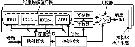
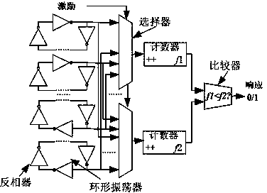
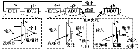
[0038] Such as figure 1 As shown, the present invention discloses a physically unclonable function based on a reconfigurable ring oscillator, including a mapping module, a control module and a reconfigurable ring oscillator matrix, wherein the reconfigurable oscillator matrix is ​​the most important module , is also a module that consumes the most resources. It is used to extract the delay difference between the logic circuit and the connection and generate a response signal. Each reconfigurable bit generator is composed of a reconfigurable oscillation loop, a counter, a register and a comparator. , the reconfigurable oscillator matrix is ​​composed of a certain number of reconfigurable bit generators, the number of which is determined by the actual application requirements, for example, after each operation, it is required to generate a 64-bit or ...


PUM


Abstract

The invention discloses a physical unclonable function based on reconfigurable ring oscillators and a generation method of the physical unclonable function based on the reconfigurable ring oscillators. The physical unclonable function comprises a reconfigurable ring oscillator matrix, a mapping module and a control module. The reconfigurable ring oscillator matrix is formed by reconfigurable bit generators, wherein the number of the bit generators in the matrix is determined according to the requirement in practical application. Each reconfigurable bit generator is formed by a reconfigurable oscillation loop, a counter, a register and a comparator. The reconfigurable ring oscillator matrix can extract random differences introduced between gate circuits in the manufacturing and machining processes and can generate random response signals. The mapping module has the function of generating a pair of configuration signals corresponding to each excitation signal for each excitation signal. The control module controls and coordinates work of the mapping module and work of the configurable ring oscillator matrix. Compared with a physical unclonable function based on the traditional ring oscillators, hardware implementation cost is greatly reduced, and the physical unclonable function has wider application prospects in safety fields such as the encryption authentication field.

Description


Claims


Application Information

Patent Timeline
Owner NANJING UNIV OF AERONAUTICS & ASTRONAUTICS
Learn More