Dust removing device

A technology of a dust removal device and body, which is applied to a cyclone device, a device whose axial direction of the cyclone can be reversed, etc., can solve problems such as the inability to meet the large-scale requirements of the dust collector, the limitation of the application effect of the cyclone dust collector, and the reduction of the dust removal efficiency. , to achieve the effect of improving dust removal work efficiency, organizing airflow conditions, and improving dust removal efficiency

Inactive Publication Date: 2014-12-10
ANHUI CONCH KAWASAKI ENERGY CONSERVATION EQUIP
View PDF7 Cites 0 Cited by
  • Summary
  • Abstract
  • Description
  • Claims
  • Application Information

AI Technical Summary

Problems solved by technology

However, the dust removal efficiency of the existing cyclone dust collector is about 85%, and it is difficult to enlarge it, because usually, the diameter of the cylinder of the cyclone dust collector increases, and the dust removal efficiency will also decrease.
This limits the applicable effect of the cyclone dust collector. On the one hand, it reduces the use efficiency, and on the other hand, it cannot meet the large-scale requirements of the dust collector in actual production.

Method used


Image

  • Dust removing device
  • Dust removing device

Examples


Embodiment Construction

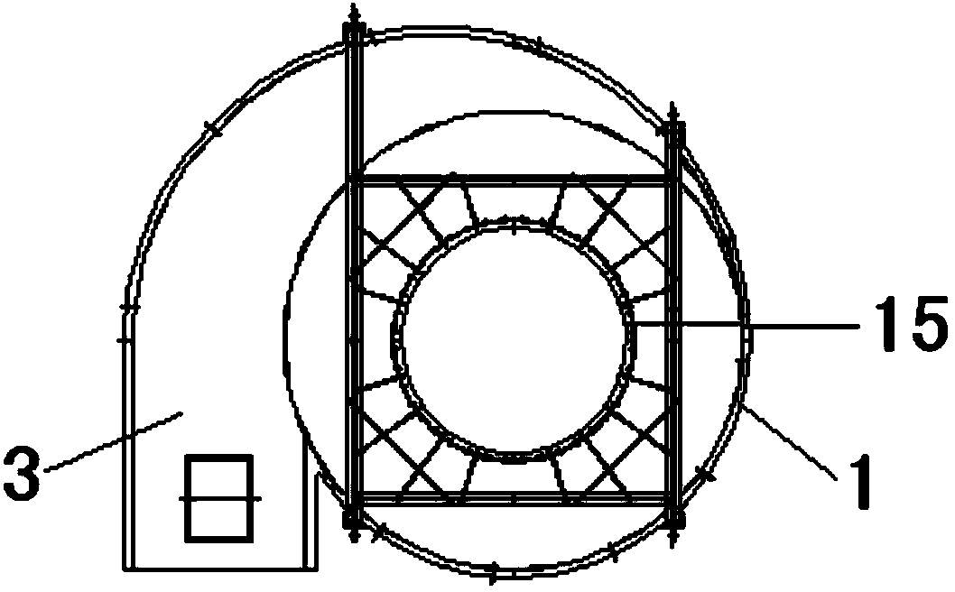
[0016] Below with reference to the accompanying drawings, through the description of the embodiments, the specific embodiments of the present invention, such as the shape, structure, mutual position and connection relationship between the various parts, the role and working principle of the various parts, etc., will be further described. Detailed instructions:

[0017] as attached figure 1 , with figure 2 As shown, the present invention is a dust removal device. The dust removal device includes a cylindrical device body 1 and a lower cylinder body 2. The lower part of the device body 1 communicates with the lower cylinder body 2 of a conical structure. The dust removal device It also includes a cylindrical flue gas inlet pipe 3, the inlet pipe bottom plate 4 of the flue gas inlet pipe 3 is set to a structure in which the height of the outer side of the bottom plate 5 is higher than that of the outer side of the bottom plate 6 connected to the device body 1, and the lower cyl...


PUM


Abstract

The invention provides a dust removing device, relating to the technical field of dust-containing gas dust removing equipment. The dust removing device comprises a cylindrical device body (1), wherein an inlet pipe bottom plate part (4) of a flue gas inlet pipe (3) of the dust removing device is of a structure in which a bottom plate outer side part (4) is higher than a bottom plate inner side part (6) connected with the device body (1); a lower barrel (2) comprises an upper conical barrel (7) and a lower conical barrel (8); and the device body (1) and the lower conical barrel (8) are communicated with an upper opening (9) of the upper conical barrel and a lower opening (10) of the upper conical barrel respectively. The dust removing device provided by the invention can realize a secondary separation effect; separated dust can be prevented from being carried by inner vortexes, so that the dust removing efficiency is improved; the flue gas inlet pipe adopts a special-shaped inlet structure so that the mutual interference between inlet gas and the inner vortexes is avoided; and gas flow working conditions in the dust removing device are effectively organized and the dust removing efficiency is improved.

Description

technical field [0001] The invention belongs to the technical field of dust removal equipment for dusty gas, and more specifically relates to a dust removal device. Background technique [0002] In the field of dusty gas dust removal equipment, cyclone dust collectors have been widely used. However, the dust removal efficiency of the existing cyclone dust collector is about 85%, and it is difficult to enlarge it, because usually, the diameter of the cylinder of the cyclone dust collector increases, and the dust removal efficiency will decrease accordingly. This limits the application effect of the cyclone dust collector. On the one hand, it reduces the use efficiency, and on the other hand, it cannot meet the large-scale requirements of the dust collector in actual production. Contents of the invention [0003] The technical problem to be solved by the present invention is to provide a dust removal device with a simple structure, which can satisfy the dust removal of larg...

Claims


Application Information

Patent Timeline
IPC IPC(8): B04C5/00B04C5/081B04C5/04B04C5/103
Inventor 肖杰玉卫明孙斌张树琛瞿建昌许昊
Owner ANHUI CONCH KAWASAKI ENERGY CONSERVATION EQUIP
Why Eureka
Try Eureka