
Main shaft for machine tool, machine tool, and method for preventing machine tool from being worn

A spindle and machine tool technology, applied in the field of wear prevention, can solve the problems that the precision machining accuracy of parts is difficult to meet the requirements, the smoothness of the spindle rotation is deteriorated, and the product qualification rate is reduced. low effect

Inactive Publication Date: 2014-12-03
BEIJING HIGH PRECISION TECH DEV
View PDF6 Cites 4 Cited by
  • Summary
  • Abstract
  • Description
  • Claims
  • Application Information

AI Technical Summary

Problems solved by technology

Relying on traditional manual or semi-automatic operation methods cannot meet the needs of the development of science and technology today. In the precision machining process of machine tools such as turning, milling, and grinding, the stability of the spindle rotation and the degree of wear of the spindle determine the quality of the parts. Precision Machining Accuracy
The main shaft of the machine tool equipment in the prior art is mainly supported by bearings, and there is serious mechanical friction and wear. With the increase of processing time, the stability of the main shaft rotation becomes worse, the precision machining accuracy of parts is difficult to meet the requirements, and the product qualification rate will decrease. As it decreases, the generation cost will further increase and other issues

Method used


Image

  • Main shaft for machine tool, machine tool, and method for preventing machine tool from being worn

Examples


Embodiment Construction

[0020] Embodiments of the present invention are described in detail below, examples of which are shown in the drawings, wherein the same or similar reference numerals designate the same or similar elements or elements having the same or similar functions throughout. The embodiments described below by referring to the figures are exemplary only for explaining the present invention and should not be construed as limiting the present invention.

[0021] In describing the present invention, it should be understood that the terms "center", "longitudinal", "transverse", "upper", "lower", "front", "rear", "left", "right", " The orientations or positional relationships indicated by "vertical", "horizontal", "top", "bottom", "inner", "outer", etc. are based on the orientation or positional relationships shown in the drawings, and are only for the convenience of describing the present invention and simplifying Describes, but does not indicate or imply that the device or element referred...


PUM


Abstract

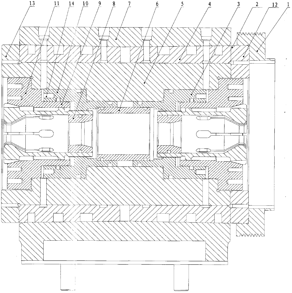
The invention discloses a main shaft for a machine tool, the machine tool, and a method for preventing the machine tool from being worn. A radial air bearing of the main shaft for the machine tool is supported in a main shaft box body, one end of the radial air bearing is connected with the end face of an air floating shaft on the front end face, and the other end of the radial air bearing is connected with the end face of an air floating shaft on the rear end face; a piston is connected with an air floating main shaft; an air floating main shaft piston is connected with a guiding chuck; a side floating disc is connected with the air floating main shaft; the air floating main shaft piston, a taper sleeve and the guiding chuck are connected onto the air floating main shaft; gas is contained in the main shaft. The main shaft for the machine tool is utilized, so that the problem that the main shaft of machine tool equipment in the prior art is mainly mechanically supported by the bearing, and the mechanical wear is severe can be solved; the occurrence of the phenomenon that the rotation stability of the main shaft gets worse along with the increase of processing time can be effectively prevented; the precision machining accuracy and the yield of the product are improved; the production efficiency is further improved remarkably and the production cost is reduced.

Description

technical field [0001] The invention relates to the field of mechanical technology, in particular to a main shaft for a machine tool, a machine tool and a method for preventing wear of the machine tool. Background technique [0002] With the development of science and technology, the demand for various machine tool equipment is increasing, and the precision requirements for machine tool equipment are getting higher and higher. Relying on traditional manual or semi-automatic operation methods cannot meet the needs of the development of science and technology today. In the precision machining process of machine tools such as turning, milling, and grinding, the stability of the spindle rotation and the degree of wear of the spindle determine the quality of the parts. Precision machining accuracy. The main shaft of the machine tool equipment in the prior art is mainly supported by bearings, and there is serious mechanical friction and wear. With the increase of processing time,...

Claims


Application Information

Patent Timeline
IPC IPC(8): B23B19/02
CPCB23Q1/70
Inventor 李金明焦尚才刘红兵张燕
Owner BEIJING HIGH PRECISION TECH DEV
Learn More