
Spray packing tower for flue gas waste heat recovery

A technology of spraying packing and waste heat of flue gas is applied in the field of spraying and packing tower, which can solve the problems of serious corrosion of heat exchange between flue gas and refrigerant, low utilization efficiency of waste heat of spray cooling water, instability of waste heat utilization of the system, etc. Achieve excellent energy-saving benefits, increase the contact heat exchange area and contact time, and reduce the effect of spray water flow

Active Publication Date: 2014-12-03
BEIJING YUANSHEN ENERGY SAVING TECH
View PDF4 Cites 10 Cited by
  • Summary
  • Abstract
  • Description
  • Claims
  • Application Information

AI Technical Summary

Problems solved by technology

[0003] To sum up, there are at least the following problems in the prior art: the pressure head of the fan and the water pump is relatively large in the direct contact heat exchange of the empty tower spray, and the power consumption of the fan and the water pump is too high; in addition, the outlet temperature of the spray cooling water The waste heat utilization efficiency is low, the flue gas flow field in the tower is very uneven, and even in some cases, serious flue gas deviation and backflow occur in the tower, resulting in instability and a significant drop in efficiency of waste heat utilization in the system. There are also problems of severe corrosion, blockage and scaling in the heat exchange between the flue gas and the refrigerant wall, as well as the problems of large investment and short life of the equipment; it is difficult to significantly reduce the emission of pollutants such as nitrogen oxides

Method used


Image

  • Spray packing tower for flue gas waste heat recovery
  • Spray packing tower for flue gas waste heat recovery
  • Spray packing tower for flue gas waste heat recovery

Examples


Embodiment 1

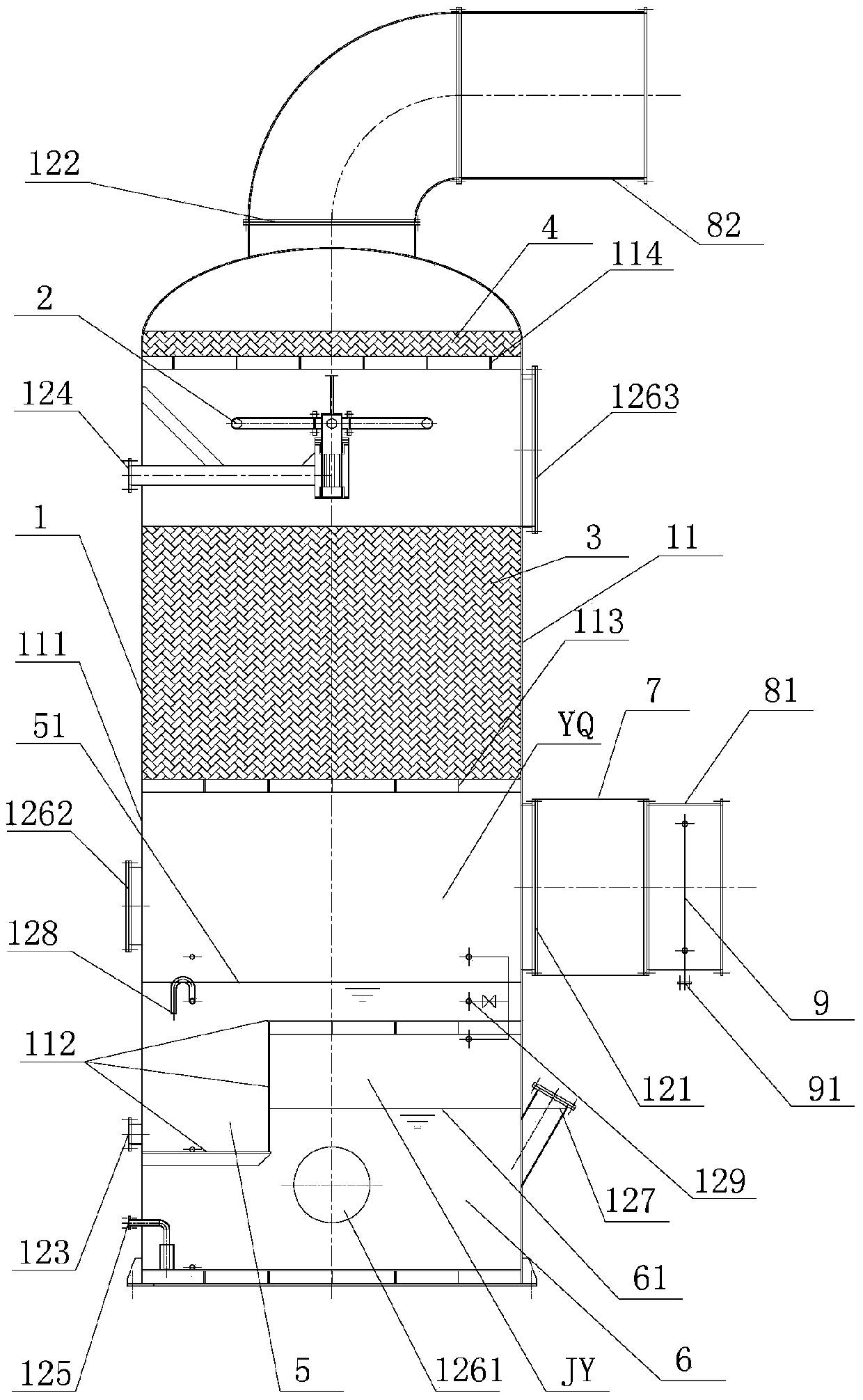
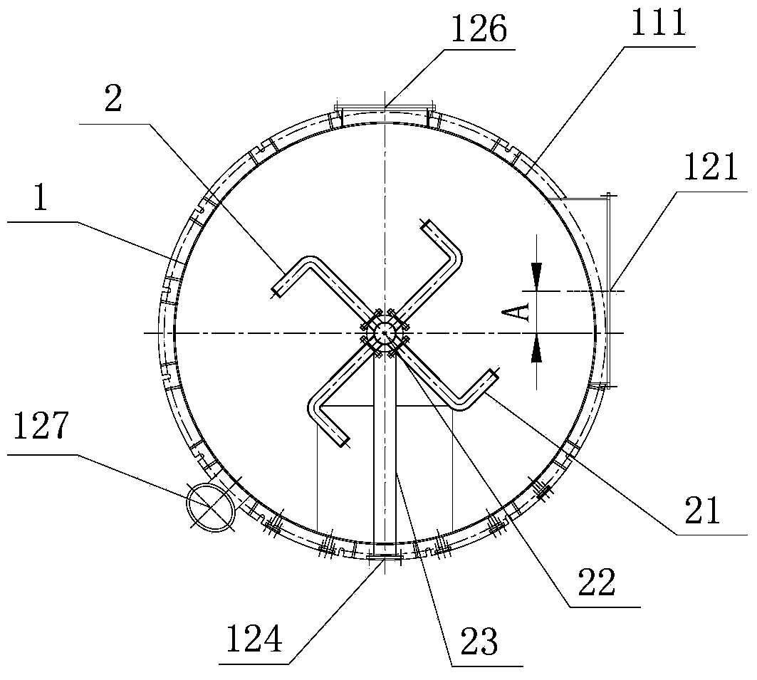
[0030] Such as figure 1 and figure 2 As shown, the present invention proposes a spray packing tower for flue gas waste heat recovery, which is characterized in that the spray packing tower for flue gas waste heat recovery includes: a spray packing tower main body 1, a spray assembly 2 , filler 3, water eliminator 4, fan 7, flue gas pipeline and oxidant distributor 9, among which:

[0031] The main body 1 of the spray packed tower comprises: the main body structural member 11 of the spray packed tower composed of the outer casing 111 of the spray packed tower, the middle partition plate 112 of the spray packed tower, the packing support plate 113 and the water eliminator support plate 114, and The main body interface of the spray packed tower arranged on the main structure part 11 of the spray packed tower;

[0032] The main interface of the spray packing tower includes: flue gas inlet 121, flue gas outlet 122, spray circulating water outlet 123, spray circulating water inle...

Embodiment 2

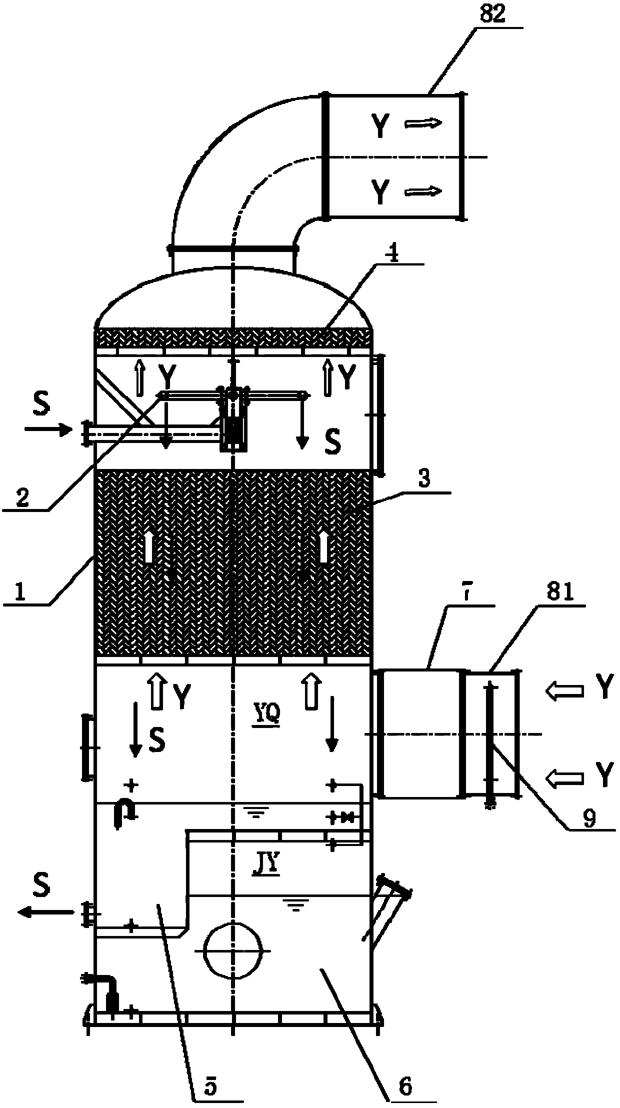
[0052] Figure 4 It is a schematic structural diagram of a spray-packed tower for flue gas waste heat recovery according to Embodiment 2 of the present invention. The difference between the second embodiment and the first embodiment is that the fan 7 of the first embodiment is connected with the pipe 81 where the flue gas enters the spray packed tower, while the fan 7 of the second embodiment is connected with the pipe 81 where the flue gas goes out of the spray packed tower 82 are connected. The temperature of the transported flue gas in the fan 7 of the first embodiment is relatively high but the flue gas has not yet reached saturation. The advantage is that the transported flue gas does not condense and has less corrosion. The efficiency will be reduced, and the high temperature will also bring some heat dissipation problems to the equipment that need to be considered. The temperature of the transported flue gas in the fan 7 of the second embodiment is relatively low but ...


PUM

PropertyMeasurementUnit
Thicknessaaaaaaaaaa

Abstract

The invention provides a spray packing tower for flue gas waste heat recovery. The spray packing tower comprises a spray packing tower main body (1), a spray component (2), packing (3), a dehydrator (4), a fan (7), a flue gas pipeline and an oxidizer distributor (9), wherein an intermediate spray packing tower partition board (112), a packing support board (113) and a dehydrator support board (114) are arranged in the spray packing tower main body (1) from bottom to top; an inner cavity of the spray packing tower main body (1) is divided into a lower alkali liquor storage space and an upper flue gas spray heat exchange space by the intermediate spray packing tower partition board (112), and the intermediate spray packing tower partition board (112) is used for receiving spray water for spray heat exchange. The spray packing tower can be used for significantly reducing the electric power of the fan for conveying flue gas and a water pump for conveying the spray water, increasing the heat energy utilization efficiency and improving the energy energy-conserving benefit.

Description

technical field [0001] The invention relates to a spray packing tower for recovering waste heat of flue gas, in particular to a spray packing tower for recovering waste heat of low-temperature flue gas of a gas boiler. Background technique [0002] At present, there are two main methods of heat exchange equipment widely used in low-temperature flue gas recovery devices: direct contact heat exchange between empty tower spray and flue gas, and heat exchange between flue gas and refrigerant partition wall. For the heat exchange equipment of the low-temperature flue gas recovery device in which the empty tower spray and the flue gas are directly contacted for heat exchange, the cooling water is sprayed into fine mist beads, and the fine mist beads are placed in the empty tower (or called a heat exchanger) Direct contact heat exchange with flue gas, which is characterized by spraying cooling water into fine mist beads and slowly falling in the empty tower. Usually, the sprayed mi...

Claims


Application Information

Patent Timeline
IPC IPC(8): B01D53/78B01D53/76B01D53/60F28C1/00F28F25/06F28F25/08
Inventor 谢正和孟继安朱迎春王正兴贾向东隋晓峰赵岩
Owner BEIJING YUANSHEN ENERGY SAVING TECH
Learn More