Line leak detector and method of using same

A detector, pipeline technology, applied in the field of leak detection, which can solve the problems of increasing customer dissatisfaction, slow fuel, increasing dispensing time, etc.

Inactive Publication Date: 2014-11-26
OPW FUEL MANAGEMENT SYST
View PDF9 Cites 4 Cited by
  • Summary
  • Abstract
  • Description
  • Claims
  • Application Information

AI Technical Summary

Problems solved by technology

[0008] Although the leak detectors described above are generally functional for their intended purpose, there are a number of disadvantages that make the use of such devices problematic in fuel dispensing operations.
For example, such leak detectors generally correspond to "choke points" throughout the distribution system that restrict the delivery of fuel to the distribution unit
As a result, the delivery of fuel to motor vehicles and the like may appear relatively slow, causing increased dispensing times and increased customer dissatisfaction
Furthermore, the effects of this flow restriction can be exacerbated when there are multiple users on a single fluid conduit line

Method used


Image

  • Line leak detector and method of using same
  • Line leak detector and method of using same
  • Line leak detector and method of using same

Examples


Embodiment Construction

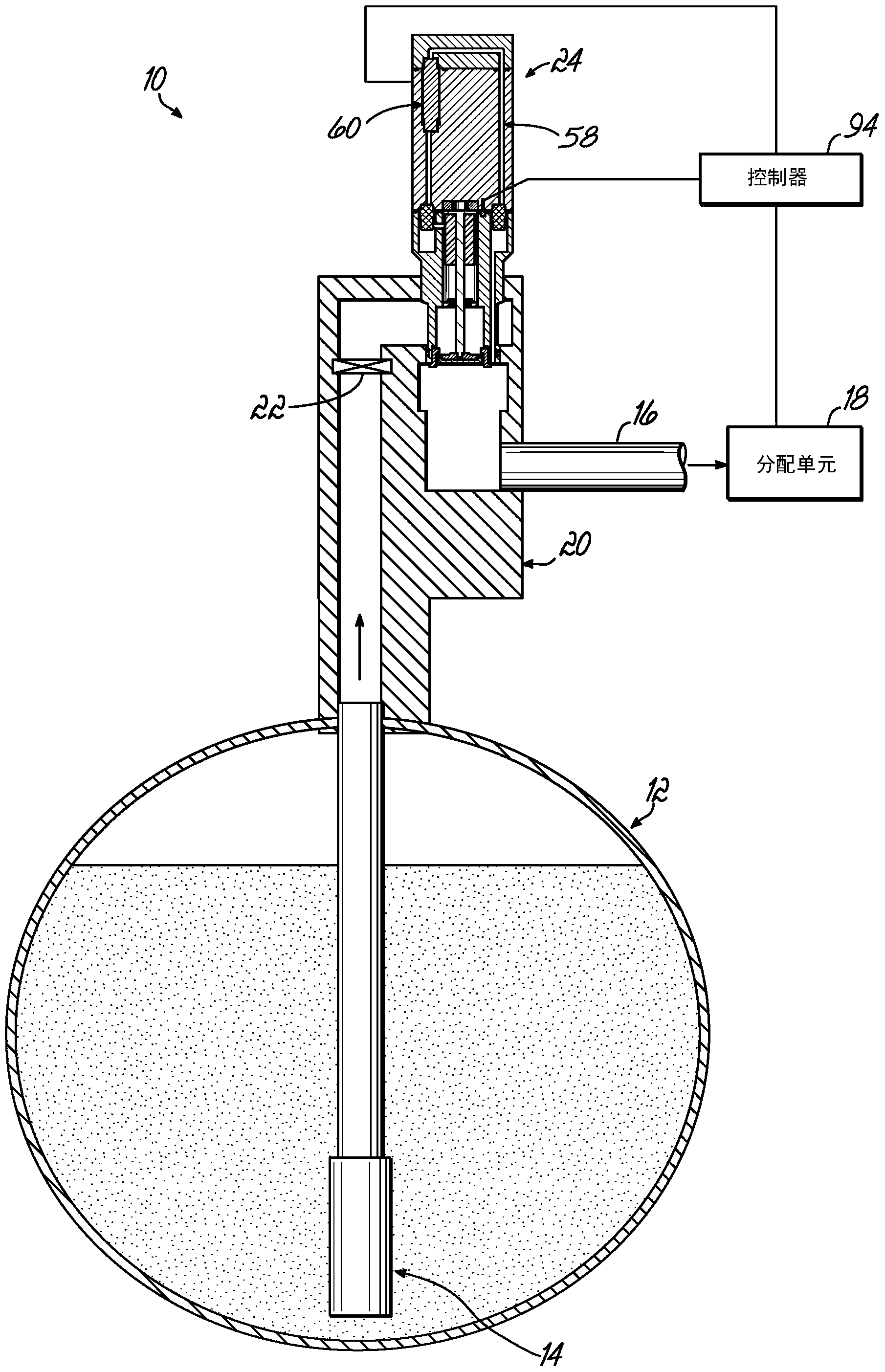
[0024] figure 1An exemplary fuel dispensing system 10 according to an embodiment of the present invention is shown in , and generally includes an underground storage tank ("UST") 12 for storing fuel, an immersion pump 14 located in the tank 12, and pressurized fuel The fluid conduit line 16 delivered to one or more distribution units 18, the one or more distribution units 18 in figure 1 is schematically shown in . Typically, fluid conduit line 16 is coupled to immersion pump 14 via a pump manifold 20, which is typically located outside tank 12, such as in a covered walkway (not shown). The pump manifold 20 may include a check valve 22 for preventing fuel from flowing back into the tank 12 . Since the check valve 22 prevents any fuel from flowing back into the tank 12 when the dispensing unit 18 is closed or closed thereby preventing fuel from flowing from the conduit line 16, the fluid conduit line 16 defines a closed system containing a quantity or volume of fuel , the clo...


PUM


Abstract

An apparatus for detecting a leak in a conduit line includes a housing in fluid communication with the line, a valve including a valve seat and a valve element movable relative to the seat between opened and closed positions, a bypass line around the valve, a flow detector coupled to the bypass line for detecting fluid flow therethrough, and a mechanism configured to urge the valve element toward the closed position and to maintain the valve element in the closed position until a threshold pressure drop is reached. The mechanism may operate on the principle of magnetism.

Description

technical field [0001] The present invention relates to leak detection and has particular application to the detection of leaks in pressurized fuel delivery lines in dispensing operations such as in filling stations. Background technique [0002] Spills of petroleum products, including gasoline, into the environment can damage environmental soil and water. Once a leak is detected, cleaning or remediation can be costly and time consuming. Therefore, it is desirable to identify leaks as early as possible. [0003] In distribution operations such as gas stations, fuel is typically stored in underground storage tanks ("USTs") from where it is pumped through various conduit lines to above-ground distribution units for distribution to motor vehicles, etc. middle. Fuel leaks from tanks or from interconnected conduit lines to dispensers can cause significant environmental damage. The United States Environmental Protection Agency ("EPA"), as well as many foreign watchdog agencies...

Claims


Application Information

Patent Timeline
Patent Type & Authority Applications(China)
IPC IPC(8): G01F1/68
CPCG01M3/144G01M3/2892Y10T137/7358
Inventor 伊恩·F·贾维
Owner OPW FUEL MANAGEMENT SYST
Why Eureka
Try Eureka