Groove-type metallized half hole and manufacturing method thereof

A technology of metallized half-holes and manufacturing methods, applied in the direction of electrical connection formation of printed components, electrical connection of printed components, printed circuit components, etc., can solve problems such as limited bonding force, bridging short circuit, copper thorn residue, etc., to improve durability The effect of mechanical external force capability, avoiding open circuit and improving welding strength

Inactive Publication Date: 2017-09-12
GUANGDONG SHENGYI SCI TECH
View PDF6 Cites 0 Cited by
  • Summary
  • Abstract
  • Description
  • Claims
  • Application Information

AI Technical Summary

Problems solved by technology

[0003] like figure 1 , figure 2 As shown, in the traditional half-hole plate, a metallized layer 3 ′ is formed on the hole wall of the half-hole 2 ′ formed on the side wall of the substrate layer 1 ′. The bonding force between the metallized layer 3 ′ and the hole wall is limited, and the It affects the ability of side wall welding to resist mechanical external force
On the other hand, when forming a half-hole, the direction of rotation of the milling cutter is clockwise. Therefore, when the cutter reaches point A, since the metallization layer 3` at point A is closely connected with the base layer 1`, the The metallized layer 3` attached to the hole wall has support, which can prevent the extension of the metallized layer 3` during processing and the separation from the hole wall, so as to ensure that there will be no copper thorn residue after processing here; and when the tool is processed to At point B, since the metallized layer 3` attached to the hole wall does not have any support, the metallized layer 3` is easily curled in the direction of tool rotation due to the influence of external force during the forward movement of the tool, resulting in the metallized layer 3` Pulled off, warped, damaged, and copper thorn residues will directly affect the customer's installation and use; in addition, the copper wire remaining in the half hole is prone to weak solder joints, virtual soldering, and bridging during the welding process. Short circuit and other problems

Method used


Image

  • Groove-type metallized half hole and manufacturing method thereof
  • Groove-type metallized half hole and manufacturing method thereof
  • Groove-type metallized half hole and manufacturing method thereof

Examples


Embodiment Construction

[0034] Embodiments of the present invention will now be described with reference to the drawings, in which like reference numerals represent like elements.

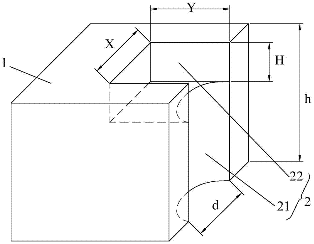
[0035] Such as image 3 , Figure 10 As shown, the groove-type metallized half-hole 2 provided by the present invention is arranged at the side wall of the PCB board 1. The groove-type metallized half-hole 2 includes a half-hole 21, and the half-hole 21 is along the PCB The thickness direction is set on the side wall of the PCB board 1, the aperture of the half hole 21 is d, the thickness of the PCB board 1 is h, and the upper end of the half hole 21 expands to form a positioning groove 22, so The length, width, and depth of the positioning groove 22 are X, Y, and H respectively, and X≥d, Y>d / 2, H

[0036]...


PUM


Abstract

The invention discloses a groove-type metallized half hole, which includes a half hole opened on the side wall along the thickness direction of a PCB board. The diameter of the half hole is d, and the thickness of the PCB board is h. Positioning groove, the length, width, and depth of the positioning groove are X, Y, and H respectively, and X≥d, Y>d / 2, H<h, and the hole wall of the half hole and the inner wall of the positioning groove are provided in one piece The metal layer of formula structure, wherein, d, h, X, Y, H are all real numbers greater than zero. The groove-shaped metallized half hole greatly improves the welding strength of the hole wall and the mechanical external force resistance of the side wall welding due to the increase of the welding surface in the X and Y directions, and greatly improves the reliability of welding and assembly. The invention also discloses a method for manufacturing groove-shaped metallized half-holes. When making groove-shaped metallized half-holes by this method, the metal layer is not easy to curl in the direction of tool rotation, and will not be pulled off, warped, damaged, or copper thorns Residue, effectively improve the open circuit and short circuit problems during welding, and improve welding reliability.

Description

technical field [0001] The invention relates to the technical field of PCB boards, in particular to a groove-shaped metallized half hole of a PCB board and a processing method thereof. Background technique [0002] Half-hole board is a special type of circuit board product that makes full use of the three-dimensional space of the circuit board and conducts or connects with electronic components on its side wall. The half-hole not only retains the conduction function of the round hole, but also can use the The hole wall is welded and fixed, which realizes the function of fixing parts or components through a simple and convenient structure. For example, the sub-mother board, the sub-board is generally used to mount the chip, and the sub-board after the chip is mounted is used as a component and then mounted on the motherboard. In order to realize this structure, it is necessary to process a metallized half-hole on the sub-board. The pins of the chip are fixed in the metallize...

Claims


Application Information

Patent Timeline
Patent Type & Authority Patents(China)
IPC IPC(8): H05K1/11H05K3/42
Inventor 邹传旺郑军
Owner GUANGDONG SHENGYI SCI TECH
Why Eureka
Try Eureka