
Vibrating diaphragm forming mold base and vibrating diaphragm forming mold including the mold base

A technology of forming molds and forming seats, which is applied in the direction of sensors and electrical components, can solve the problems of easy wrinkling of the diaphragm, improper forming of the diaphragm, and poor stability, and achieve excellent acoustic performance, clear outline, and high stability.

Active Publication Date: 2014-11-26
GOERTEK INC
View PDF4 Cites 7 Cited by
  • Summary
  • Abstract
  • Description
  • Claims
  • Application Information

AI Technical Summary

Problems solved by technology

This single-material diaphragm forming mold seat is easy to manufacture, but the diaphragm is formed at high temperature, and the diaphragm includes a ball top and a ring part, and the ring part is composed of a straight edge part and a corner part. The shape and structure are different, and the role played by the diaphragm is also different, so the technical requirements for temperature and pressure are not the same for each part during processing. There are limitations in this aspect, which cannot meet the technical requirements of different parts of the diaphragm, resulting in the following defects in the produced diaphragm:
[0003] 1. The diaphragm has good resilience and is not easy to wrinkle, but the contour of the straight edge area of ​​the diaphragm is not clear enough, and the diaphragm is not well formed
[0004] 2. The forming effect of the vibrating membrane is good, but the vibrating membrane is easy to wrinkle, and it is not easy to recover after wrinkling
[0005] It can be seen from the above two points that it is difficult to balance the performance of the mold and the performance of the product with a single-material diaphragm forming mold seat, resulting in defects such as poor acoustic performance and poor stability of the formed diaphragm

Method used


Image

  • Vibrating diaphragm forming mold base and vibrating diaphragm forming mold including the mold base
  • Vibrating diaphragm forming mold base and vibrating diaphragm forming mold including the mold base
  • Vibrating diaphragm forming mold base and vibrating diaphragm forming mold including the mold base

Examples


Embodiment 1

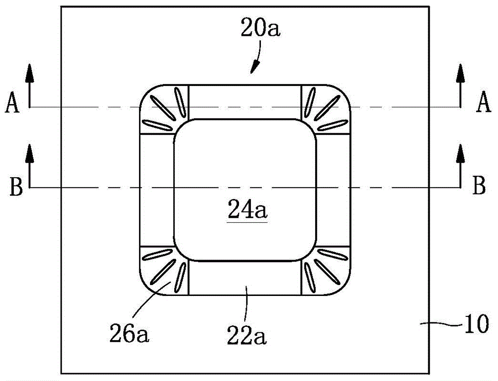
[0030] Such as figure 1 As shown, a diaphragm forming mold seat includes a diaphragm forming seat 20a consistent with the structure of the diaphragm to be processed, and a base 10 is arranged around the diaphragm forming seat 20a, and the diaphragm forming seat 20a and the base 10 is integrated, and the diaphragm molding seat 20a includes a straight side part 22a, a corner part 26a and a spherical top part 24a that are combined together.

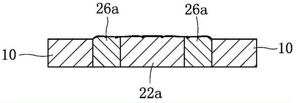
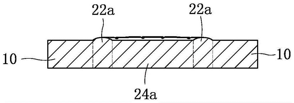
[0031] Such as figure 2 and image 3 Commonly shown, the straight edge portion 22a, the corner portion 26a and the dome top 24a are processed from two kinds of materials such as aluminum, copper, stainless steel and air-permeable steel, wherein the materials of the straight edge portion 22a and the corner portion 26a are different, straight The side 22a is made of the same material as the dome top 24a. In this embodiment, it is preferable that both the straight edge portion 22a and the spherical top portion 24a are made of aluminum, and ...

Embodiment 2

[0035] This embodiment is basically the same as Embodiment 1, the difference is that:

[0036] Such as Figure 4 , Figure 5 and Figure 6 As shown collectively, the diaphragm molding seat 20b includes a straight edge portion 22b, a corner portion 26b and a spherical top portion 24b. The straight edge portion 22b, the spherical top portion 24b and the corner portion 26b are separately processed from three materials among aluminum, copper, stainless steel and air-permeable steel. In this embodiment, preferably, the straight edge portion 22b is processed from aluminum, the ball top 24b is processed from copper, and the corner portion 26b is processed from air-permeable steel.

[0037] Such as Figure 6 As shown, the straight edge portion 22b is made of the same material as the base 10, which is aluminum.

[0038] Such as Figure 4 , Figure 5 and Figure 6 As shown together, the base 10 and the straight side part 22b have an integrated structure, which is formed by one-t...


PUM


Abstract

The invention discloses a vibrating diaphragm forming mold base and a vibrating diaphragm forming mold including the mold base, and relates to the technical field of electric-acoustic product machining molds. The mold base comprises a vibrating diaphragm forming base which is the same as a vibrating diaphragm in structure, pedestals are arranged around the vibrating diaphragm forming base, and the vibrating diaphragm forming base and the pedestals are combined together. The vibrating diaphragm forming base comprises straight side parts, corner parts and a globe roof part which are combined together. The straight side parts, the corner parts and the globe roof part are made of at least two metal materials. The vibrating diaphragm forming mold base is made of different materials, the limitations of a single material on the aspects of thermal expansion and thermal transmission are removed, and the produced vibrating diaphragm is clear in outline, good in rebound resilience, not prone to wrinkling, excellent in acoustic performance and high in stability.

Description

technical field [0001] The invention relates to the technical field of electroacoustic product processing molds, in particular to a diaphragm forming mold seat and a diaphragm forming mold including the mold seat. Background technique [0002] The diaphragm is an important part of the micro-speaker, which plays a vital role in the sound reproduction performance of the micro-speaker, and it determines the conversion quality of the speaker from electricity to sound. The forming of the diaphragm is usually by placing the diaphragm between the forming mold seat and the mold head, and then forming it by high temperature and pressure. Existing diaphragm forming mold seats are all made of a single material, generally aluminum, copper or stainless steel. This single-material diaphragm forming mold seat is easy to manufacture, but the diaphragm is formed at high temperature, and the diaphragm includes a ball top and a ring part, and the ring part is composed of a straight edge part ...

Claims


Application Information

Patent Timeline
IPC IPC(8): H04R31/00
Inventor 郭晓冬江超
Owner GOERTEK INC
Learn More