
'|'-shaped free surface holing one-step well completion technology

A free and technological technology, applied in shaft equipment, reverse drilling, blasting, etc., can solve the problems of affecting blasting effect, difficult operating conditions, poor safety conditions, etc. The effect of improving safety performance

Active Publication Date: 2013-09-18
安徽马钢矿业资源集团姑山矿业有限公司 +1
View PDF5 Cites 18 Cited by
  • Summary
  • Abstract
  • Description
  • Claims
  • Application Information

AI Technical Summary

Problems solved by technology

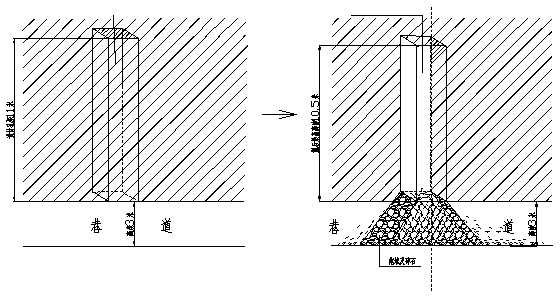
Among them, the first two methods need to excavate the cutting patio at the end of the mining roadway. At present, the construction of the cutting patio is completed by manual excavation or bottom-up blasting in stages, which has high labor intensity, poor safety conditions, long construction time and poor operating conditions. hard
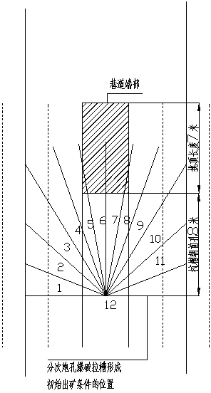
The disadvantage of the third method is that there are many blast holes, high production cost, and high labor intensity, and because this method is blasting in stages, if the previous blasting effect is not good, it will have a major impact on the free surface of the next blasting. Disposal will bring great safety risks; since the slotted blast hole is behind, the collapsed ore will be affected by the shock wave, and will collapse into the mine in large quantities, resulting in the loss of ore resources
[0003] At the same time, in the paper "One-time Well Forming and Cutting Blasting of Deep Holes", because the hole diameter is too small, and the hole spacing is ≤200mm, in actual construction, due to the influence of bias force, the holes will cross, affecting the blasting effect, resulting in well completion. fail

Method used


Image

  • '|'-shaped free surface holing one-step well completion technology
  • '|'-shaped free surface holing one-step well completion technology
  • '|'-shaped free surface holing one-step well completion technology

Examples


Embodiment Construction

[0017] The following is a further detailed introduction to the "︱-type" free surface cutting process of the present invention for one-time well formation:

[0018] (1) Rock drilling equipment and hole layout:

[0019] 1) Rock drilling equipment: use CTC-141 rock drilling rig to drill the charging hole (drill hole diameter φ60mm, after drilling diameter φ62mm), T-100 high-pressure annular down-the-hole drilling rig to drill the initial free surface hole (drill hole diameter φ115mm, After drilling, the hole diameter is φ120mm).

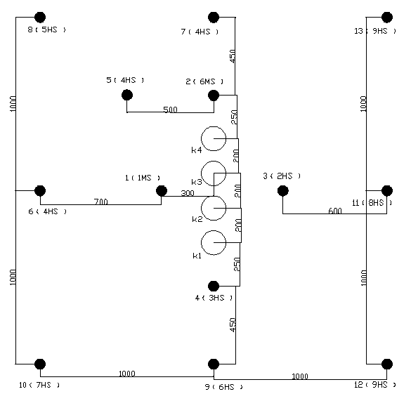
[0020] 2) Cutting method and blasting hole arrangement: Blind patio deep hole blasting requires one charge blasting to form a well and reach the design height, so the cutting is required to be reliable. In the well-forming specification with a cross-section of 2m×2m and a depth of 11m, the arrangement of cutting holes is designed to be 8, of which 4 are empty holes on the free surface and 4 are charging holes (if the hardness of the ore rock is relativ...


PUM


Abstract

The invention discloses a '|'-shaped free surface holing one-step well completion technology, which comprises the following steps: (1) confirming the holing way and arranging blasting holes, wherein holing holes and peripheral holes and assistant holes are formed in the position needed to complete the well at the end part of a mining roadway, the number of the holing holes is 8, and the total number of the peripheral holes and the assistant holes is 9; and the specific way is that four hollow holes are longitudinally formed in the center line at the end part in a '|'-shaped manner to be taken as a blasting initial free surface and compensation space, four explosive filling holes are formed in the periphery of the four hollow holes under a principle to the benefit of the forming of the groove cavity and not to mutually blast, and the nine peripheral holes and assistant holes are formed in the periphery of the groove cavity; (2) drilling; (3) filling explosive; and (4) blasting. The technology can reduce the lose of the ore, improves the ore recovery rate, can also guarantee the blasting quality, reduces the construction number of the blasting holes, reduces the groove-pulling blasting times, reduces the explosive consumption, relieves the labor intensity of the blaster, improves the safety performance, reduces the manufacturing cost, and meanwhile can also be directly used for constructing vertical wells.

Description

technical field [0001] The invention belongs to a one-time well-forming blasting process in metallurgical mines, and is suitable for excavating cutting grooves or constructing vertical shafts in underground pillar-less caving mining processes. Background technique [0002] At present, there are three main methods of excavating cutting grooves in underground mines that adopt the method of caving without pillars: ① combined trenching method of cutting level roadway and cutting patio; ② trenching method of cutting patio; Among them, the first two methods need to excavate the cutting patio at the end of the mining roadway. At present, the construction of the cutting patio is completed by manual excavation or bottom-up blasting in stages, which has high labor intensity, poor safety conditions, long construction time and poor operating conditions. hard. The disadvantage of the third method is that there are many blast holes, high production cost, and high labor intensity, and bec...

Claims


Application Information

Patent Timeline
IPC IPC(8): E21D3/00F42D1/08F42D3/00
Inventor 许宝红余剑谢其全
Owner 安徽马钢矿业资源集团姑山矿业有限公司
Learn More