Servo motor with encoder function and position detection method of servo motor with encoder function

A technology of a servo motor and a detection method, applied in the field of servo motor research, can solve the problems that cannot be overcome at the same time, and achieve the effects of improving structural strength and reliability, simplifying protective structure and compact structure

Active Publication Date: 2014-11-26
GSK CNC EQUIP
View PDF9 Cites 11 Cited by
  • Summary
  • Abstract
  • Description
  • Claims
  • Application Information

AI Technical Summary

Problems solved by technology

[0004] However, the above-mentioned improvements are only improved for one of the problems, and cannot overcome the above-mentioned two problems at the same time, and the above-mentioned two problems are key factors affecting the normal operation of the servo motor. Therefore, how to overcome the above-mentioned two problems at the same time is of great importance. research significance

Method used


Image

  • Servo motor with encoder function and position detection method of servo motor with encoder function
  • Servo motor with encoder function and position detection method of servo motor with encoder function
  • Servo motor with encoder function and position detection method of servo motor with encoder function

Examples


Embodiment 1

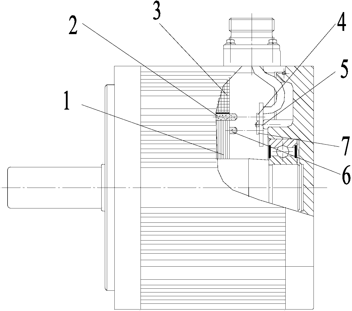
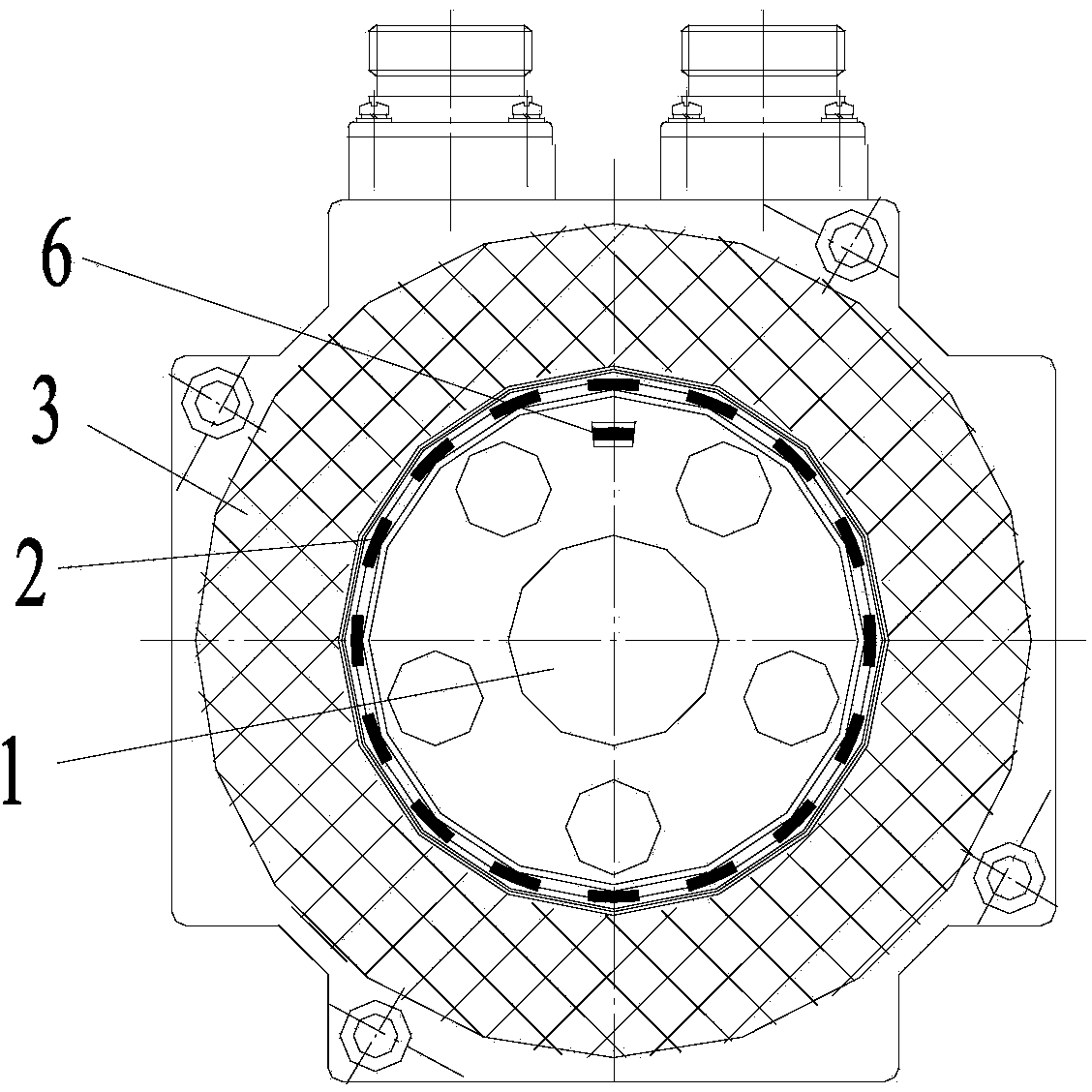
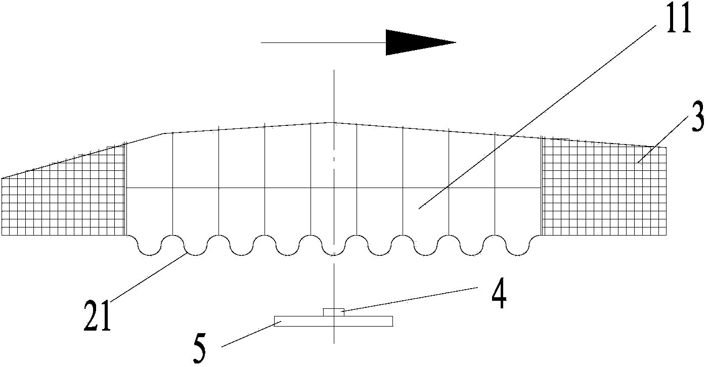
[0035] Such as figure 1 , 2 , 3, the servo motor with the encoder function described in this embodiment includes the rotor 1 and the stator 3 of the traditional motor. The present invention proposes to set the tooth structure 2 on the rotor magnetic tile 11. The tooth structure 2 of the present embodiment shape structure such as image 3 Shown in 21, it is arc-shaped. Here the toothed structure acts as the magnetic grid of the encoder.

[0036] The servo motor also includes a first Hall element 4 (Hall element A in this example), a second Hall element 8 (Hall element B in this example), a zero Hall element 7, a PCB circuit board 5 and a zero magnet 6 , wherein the first Hall element 4, the zero Hall element 7, the PCB circuit board 5, the zero magnet 6, and the positional relationship between the rotor magnetic tile 11 are as follows figure 1 , 2 , 3, the position of the zero point magnet 6 in the motor is as follows figure 2 shown.

[0037] Such as Image 6 As shown,...

example 1

[0053] Example 1: Assume that the current motor rotor rotates to the 14th magnetic grid period, and Figure 14 At point A, since point A is within the interval of 0 to T / 8, it is an increasing interval, so after AD samples sinθ and cosθ values, calculate |tanθ| value, |tanθ|=210, look up the table to get the subdivision 0X0F, the 14th magnetic grid cycle is converted to 0X0E of 16 progress, the magnetic grid cycle number is high, and the subdivision value is low, combined: 0X0E&0X0F=0X0E0F, so the current absolute position value of point A is 0X0E0F.

example 2

[0054] Example 2: Assume that the current motor rotor rotates to the 60th magnetic grid period, and Figure 14 At point B, because point B is within the interval of 5T / 8~3T / 4, it is a decreasing interval, so after AD samples the values ​​of sinθ and cosθ, calculate |cotθ| value, |cotθ|=105, look up the table The score is 0XB6, the 60th magnetic grid cycle is converted to 0X3C with 16 progress, the magnetic grid cycle number is high, and the subdivision value is low, merge: 0X3C&0XB6=0X3CB6, so the current absolute position value of point B is 0X3CB6.


PUM


Abstract

The invention discloses a servo motor with the encoder function and a position detection method of the servo motor with the encoder function. A tooth-shaped structure is arranged at the edge of a body of a rotor magnetic shoe of the servo motor, and when a rotor rotates, relative displacement is generated between the rotor magnetic shoe and Hall elements. The Hall elements include the first Hall element and the second Hall element, the first Hall element and the second Hall element right face the circumference track of movement of a magnetic grid of the rotor, and the included angle between the first Hall element and the second Hall element meets the rule of (n+ / -1 / 4)T, wherein the n is an integer, and the T represents one period of the magnetic grid. The method includes the steps that the rotor magnetic shoe rotates to generate an alternating magnetic field accordingly, the alternating magnetic field is respectively converted by the first Hall element and the second Hall element into alternating voltage signals which are output to a signal processing circuit, and the signal processing circuit converts the signals into position signals or pulse signals according to the waveform relation of the two collected signals and then outputs the signals to a servo driver. By means of the servo motor and the position detection method, the integration of the servo motor and an encoder is achieved, the structure is compact, the size is small, and meanwhile the structural strength and the reliability are high.

Description

technical field [0001] The invention relates to the research field of servo motors, in particular to a servo motor with an encoder function and a position detection method thereof. Background technique [0002] At present, in order to realize the position detection function of the traditional servo motor, an encoder is generally installed outside the motor body. This structure makes the overall volume of the motor larger. At the same time, the existing encoders are all photoelectric and magnetic, which have the disadvantages of low protection level, poor strength, and poor impact resistance. [0003] Aiming at the above two problems, researchers in this field have proposed some improved methods. For example, in view of the problem of large motor volume, the patent publication No. CN1815860A discloses a small motor with an encoder. The motor is detected by setting a driving magnet and a signal magnet, thereby realizing miniaturization. Aiming at the shortcomings of encoders...

Claims


Application Information

Patent Timeline
Patent Type & Authority Applications(China)
IPC IPC(8): H02K11/00H02K1/22H02P6/16H02K11/215H02P6/17
Inventor 何敏佳湛文亮吴维玲
Owner GSK CNC EQUIP
Why Eureka
Try Eureka