
Glass kiln flue gas de-dusting, denitrification and desulfurization integral treatment process

A glass kiln and flue gas technology, which is applied in the new process of desulfurization integrated treatment, denitrification, glass furnace flue gas dust removal, can solve the problem that the efficiency of high-temperature electric dust removal is difficult to achieve the design efficiency, and the design efficiency, investment and operation costs cannot be achieved. Large and other problems, to achieve the effects of small footprint, low heat loss, and reduced operating costs

Active Publication Date: 2014-11-26
NANJING CEEP TECH
View PDF5 Cites 11 Cited by
  • Summary
  • Abstract
  • Description
  • Claims
  • Application Information

AI Technical Summary

Problems solved by technology

However, due to the particularity of the glass industry, that is, the dust particles are extremely small and have strong viscosity, there are some common problems in this process at present: 1) the efficiency of high-temperature electrostatic precipitator is difficult to reach the design efficiency; 2) due to the problem of high-temperature electrostatic precipitator The denitrification catalyst deactivates quickly, so that the denitrification operation cannot reach the design efficiency for several months; 3) There are two dust removal processes in this process, the bag dust removal system necessary for the electric dust removal process and dry desulfurization, which makes the system redundant and causes Investment and operating costs are too large

Method used


Image

  • Glass kiln flue gas de-dusting, denitrification and desulfurization integral treatment process

Examples


Embodiment Construction

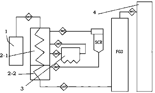
[0019] see figure 1 Flow chart:

[0020] 1) Waste heat boiler (can be a heat exchanger):

[0021] The waste heat boiler 2-1, including the second group of waste heat boiler 2-2, has three inlets and three outlets, and the three inlets are respectively the inlets of the high-temperature flue gas 1 of the glass kiln (there will be a temperature of about 500°C for the intake air) 1. The entrance of the flue gas that meets the dust removal standard and the flue gas inlet that meets the denitrification standard; the three exits are respectively entering the high-temperature dust removal section, entering the denitration section and entering the desulfurization section. Through the reasonable design and transformation of waste heat boilers, each flue gas treatment section is guaranteed to be carried out under the most suitable temperature conditions, thereby ensuring the reliability of the system; waste heat boilers can be divided into two groups, the first group of waste heat boil...


PUM


Abstract

The invention relates to a glass kiln flue gas de-dusting, denitrification and desulfurization integral treatment process. The process comprises the following steps: glass kiln high-temperature flue gas is subjected to heat absorption by using a residual heat boiler and is cooled; the flue gas is cooled to a temperature range of 250-300 DEG C through the residual heat boiler, and is delivered into a de-dusting device wherein the flue gas is subjected to de-dusting; standard flue gas after de-dusting is returned to the residual heat boiler and is heated to a selective catalytic reduction (SCR) temperature window of 300-420 DEG C, and is delivered into an SCR denitrification device; standard flue gas after denitrification is returned to the residual heat boiler where heat is recovered; when the temperature of the flue gas is approximately 120+ / -20 DEG C, the flue gas is delivered into a wet desulfurization device; and standard flue gas after a wet desulfurization treatment is discharged into the atmosphere through a chimney. According to the invention, the residual heat boiler is designed and modified, such that the boiler is provided with three sets of approximate temperature inlet and outlet, and thus various systems can work under appropriate temperature windows. Therefore, system reliability is endured, operation investment cost is reduced, and heat loss is minimized.

Description

technical field [0001] The invention relates to the field of flue gas treatment, in particular to an integrated process of dust removal, denitrification and desulfurization, especially a new process for integrated treatment of dust removal, denitrification and desulfurization of glass furnace flue gas (tail gas). Background technique [0002] With the improvement of our country's economy and living standards, more and more attention will be paid to the environment. At present, environmental problems are deteriorating day by day. In the past two years, smog has shrouded six provinces and one city in East China, and it has a tendency to spread. PM2.5 monitoring systems in various places have also exploded one after another. At present, it has attracted widespread attention from the society. . The country has also issued a series of policies in succession. The Ministry of Environmental Protection of the People's Republic of China stipulates in the "Emission Standard of Air Pol...

Claims


Application Information

Patent Timeline
Patent Type & Authority Applications(China)
IPC IPC(8): B01D53/75B01D53/56B01D53/50B01D46/02F23J15/02
Inventor 韩冰刘训稳陈勇魏敏
Owner NANJING CEEP TECH
Learn More