Piston ring for an internal combustion engine

A technology for piston rings and internal combustion engines, applied in the field of piston rings, can solve the problems of increasing manufacturing costs and material costs, and achieve the effects of prolonging wear life and reducing wear

Active Publication Date: 2014-11-19
MAHLE INT GMBH
View PDF9 Cites 0 Cited by
  • Summary
  • Abstract
  • Description
  • Claims
  • Application Information

AI Technical Summary

Problems solved by technology

A known measure against this wear is to increase the thickness of the coating at least in ...

Method used


Image

  • Piston ring for an internal combustion engine
  • Piston ring for an internal combustion engine
  • Piston ring for an internal combustion engine

Examples


Embodiment Construction

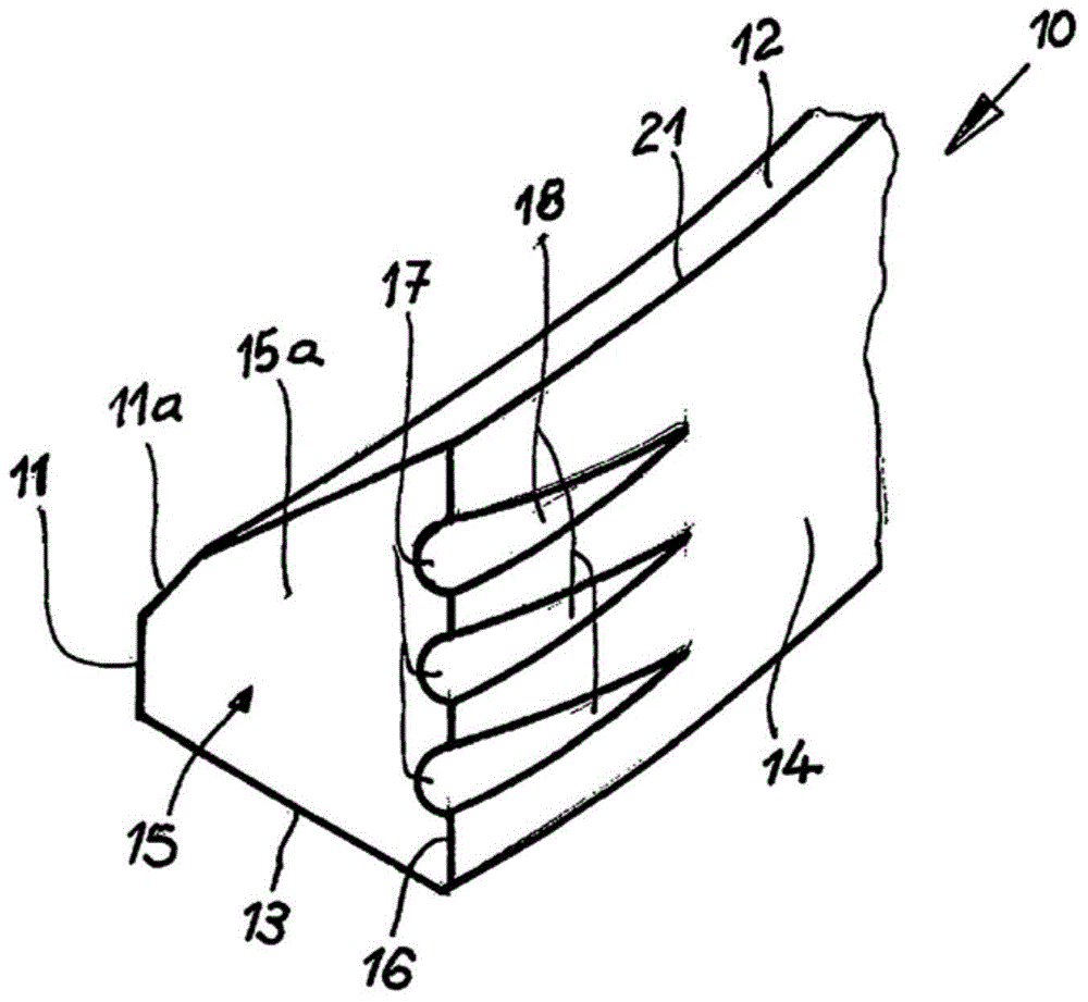
[0027] figure 1 A first embodiment of a piston ring 10 of the invention is shown. The piston ring 10 has, in a known manner, a ring back 11 provided with a bevel 11 a , an upper ring side 12 , a lower ring side 13 and a ring contact surface 14 . The ring contact surface 14 adjoins the upper ring side 12 via an edge 21 . The piston ring 10 also has two free ring butt ends which delimit a gap or ring seam in a known manner. figure 1 The ring butt end 15 is shown provided with an end face 15a. The end face 15 a adjoins the ring contact face 14 via an edge 16 . For the sake of clarity, the normally provided coating of the ring contact surface 13 , which is applied with a coating agent, in particular a friction-reducing layer, is not shown.

[0028] The piston ring 10 according to the invention has at least one opening which forms the fluid connection of the ring contact surface 14 to the ring back 11 . In the assembled piston-cylinder unit of an internal combustion engine, th...


PUM


Abstract

The invention relates to a piston ring (10, 110, 210, 310, 410, 510, 610) for pistons of internal combustion engines, having a ring running surface (14), a ring back (11), an upper ring flank (12), a lower ring flank (13), and two ring joint ends spaced apart by a gap (15). According to the invention, at least one opening (17, 121, 217, 223, 325, 407) is provided in the ring running surface (14), which opening forms a fluid connection between the ring running surface (14) and the ring back (11) or a ring flank (12, 13).

Description

technical field [0001] The invention relates to a piston ring for a piston of an internal combustion engine, which comprises a ring contact surface, a ring back, an upper ring side, a lower ring side and two ring butt ends separated by a gap. Background technique [0002] During operation of the internal combustion engine, the ring contact surfaces of the coated piston rings, especially in the area of ​​the ring butt ends of the piston rings, are subject to wear. This is due to the increased abutment of these ring butt ends against the cylinder wall. A known measure against this wear is to increase the thickness of the coating at least in the region of the ring butt ends, but this increases the manufacturing and material costs. Contents of the invention [0003] The object of the present invention is to further develop a piston ring of the same type in order to prolong the wear life in the region of its ring butt ends in as simple a manner as possible. [0004] The solut...

Claims


Application Information

Patent Timeline
IPC IPC(8): F16J9/14
CPCF16J9/14F02B3/06F05C2201/0448F02F3/00F02F3/22F05C2201/021F16J9/12
Inventor 沃尔夫冈·伊斯勒丹尼尔·洛佩斯若泽·瓦伦廷·利马·萨拉班达
Owner MAHLE INT GMBH
Why Eureka
Try Eureka