Turbine multi-stage air seal structure

A turbine and air seal technology, applied in the direction of preventing leakage, engine components, machines/engines, etc., can solve problems such as restricting the application of radial turbines and compressors, affecting the reliability of thrust bearings, and difficulty in sealing, achieving a compact structure, Ease of assembly and improved sealing effect

Active Publication Date: 2016-05-04
JIN TONG LING TECH GRP CO LTD
View PDF6 Cites 0 Cited by
  • Summary
  • Abstract
  • Description
  • Claims
  • Application Information

AI Technical Summary

Problems solved by technology

The high pressure difference between the equipment shell and the external environment makes sealing difficult and medium leakage, and the excessive axial force of the impeller affects the reliability of the thrust bearing, which limits the application of centripetal turbines and compressors

Method used


Image

  • Turbine multi-stage air seal structure
  • Turbine multi-stage air seal structure
  • Turbine multi-stage air seal structure

Examples


Embodiment Construction

[0026] Embodiments of the present invention will be further described in detail below in conjunction with the accompanying drawings.

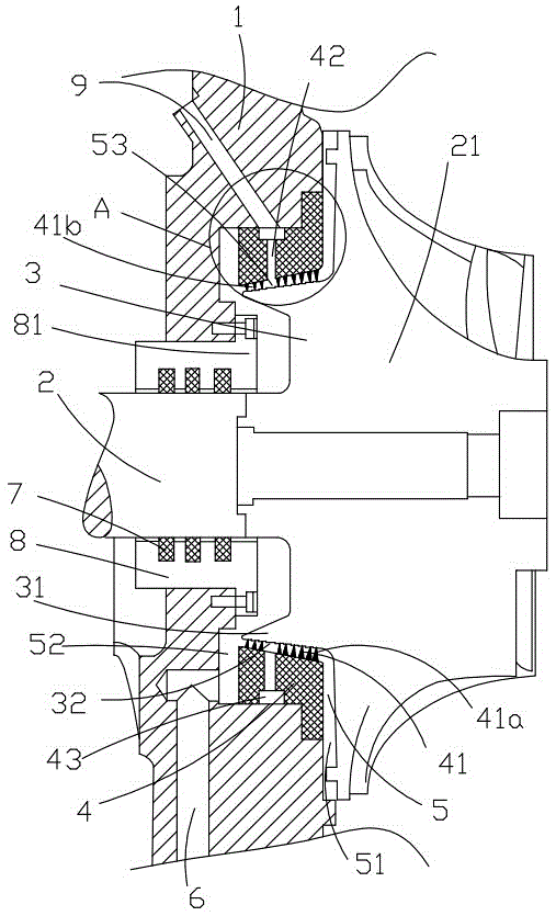
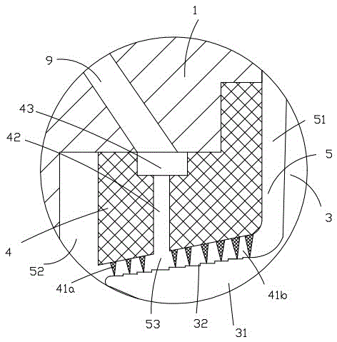
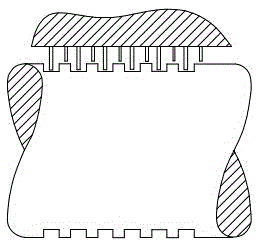
[0027] Figure 1 to Figure 2 Shown is the structural representation of the present invention. Figure 3 to Figure 4 It is a schematic diagram of a comb-teeth labyrinth seal and a multi-stage labyrinth seal in the background technology.

[0028] The reference signs are: housing 1, shaft 2, impeller 21, balance disc 3, disc convex body 31, balance piston 32, stepped seal 4, comb teeth 41, seal teeth 41a, seal cavity 41b, medium pressure Connecting cavity 42, gas collecting ring 43, isolation gap 5, high pressure gap 51, low pressure gap 52, medium pressure gap 53, low pressure air induction pipe 6, sealing floating ring 7, sealing body 8, connecting flange 81, medium pressure air induction pipe 9 .

[0029] The turbine multi-stage air seal structure of the present invention includes a casing 1 and a shaft 2 passing through the casing 1, an imp...


PUM


Abstract

The invention discloses a multistage air seal structure of a turbine. The multistage air seal structure comprises a shell and a shaft penetrating the shell, and an impeller is connected on the shaft. A balance disc is integrally formed at the rear end of the impeller, a stepped sealing element is arranged between the balance disc and the shell, a comb tooth portion is formed on the stepped sealing element and composed of a plurality of sealing teeth, the sealing teeth penetrate an isolation gap to be in seal fit with the balance disc in a butting manner, a seal cavity is formed by a space between every two adjacent sealing teeth, medium pressure gaps are formed in the middle of the comb tooth portion and are communicated with a medium pressure air leading pipe through medium pressure communication cavities formed in the stepped sealing element, and air pressure leading out form the medium pressure air leading pipe is higher than that of a low pressure gap and a high pressure gap. The multistage air seal structure has the advantages of multistage air seal, good air seal effect, convenience and simplicity in assembling and difficulty in leakage of media.

Description

technical field [0001] The invention relates to the technical field of centripetal turbines or centrifugal compressors, in particular to a turbine multistage air seal structure. Background technique [0002] The cantilever-supported centripetal turbine and centrifugal compressor have high working speed and high pressure ratio, and the shells are of integral volute structure without mid-section. From the perspective of assembly, if the main shaft is processed into a comb-toothed labyrinth, the uneven main shaft will greatly hinder the assembly of the centripetal turbine and centrifugal compressor. Therefore, the main shaft should not be processed into a comb-toothed labyrinth ( image 3 ). At the same time, from the perspective of rotor dynamics, the size of the cantilever end is required to be as small as possible to improve the rigidity of the rotor. The short axial size of the main shaft makes it difficult to arrange multi-stage labyrinth seals ( Figure 4 ). The pressur...

Claims


Application Information

Patent Timeline
Patent Type & Authority Patents(China)
IPC IPC(8): F01D11/00
Inventor 冯明飞郑晓宗周平
Owner JIN TONG LING TECH GRP CO LTD
Why Eureka
Try Eureka