Magnetic-resistance type toothless elevator traction machine

An elevator traction machine, reluctance-type technology, applied in the field of switched reluctance motors, can solve problems such as demagnetization and loss of magnetism, uneven magnetic pole distribution of magnetic steel, and increased cost, so as to reduce vibration and noise, eliminate adverse effects, The effect of improving stability

Inactive Publication Date: 2014-11-19
SUZHOU FORTUNE TECH DEV
View PDF5 Cites 9 Cited by
  • Summary
  • Abstract
  • Description
  • Claims
  • Application Information

AI Technical Summary

Problems solved by technology

[0006] The object of the present invention is to overcome the problems existing in the prior art, provide a reluctance toothless elevator traction machine, extend the application range of the servo type switched reluctance motor to the elevator traction machine, and become a reluctance toothless elevator The traction machine is suitable for the traction system of elevators such as passenger elevators, home villa elevators, and freight elevators, providing driving force for elevators; and because there is no permanent magnet, it solves the existing technical problems of permanent magnet synchronous motor elevator traction machines, such as permanent magnets Demagnetization and loss of magnetism at high temperature of the material, increased cost, unevenness of the magnetic steel causes uneven distribution of magnetic poles and affects operation, etc.

Method used


Image

  • Magnetic-resistance type toothless elevator traction machine
  • Magnetic-resistance type toothless elevator traction machine
  • Magnetic-resistance type toothless elevator traction machine

Examples


Embodiment

[0039] For the servo switched reluctance motor of the reluctance toothless elevator traction machine, when the rotor is in different positions, the phase inductance L (θ, i) is different, and the energization time of each phase winding can be changed according to the law. The size and waveform of the current produce different speeds and steering, and enter different operating states. The position detection of the controller is a closed loop. It detects the relative position between the stator and the rotor according to the position detector, and conducts the switching elements of the corresponding phase windings according to the given operation command. There is current flowing in the phase winding, and magnetic flux is generated, and the rotor is subjected to the magnetic pulling force generated by the tendency to move to the minimum reluctance position, and it rotates under the action of this force until the salient pole of the rotor turns and is drawn by it. until the attra...


PUM


Abstract

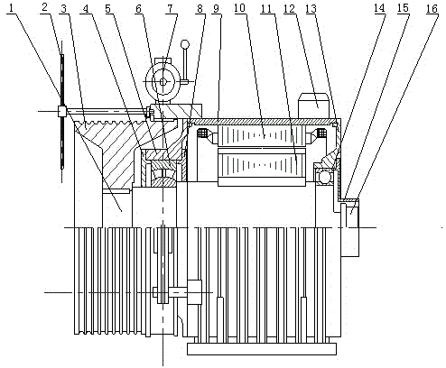
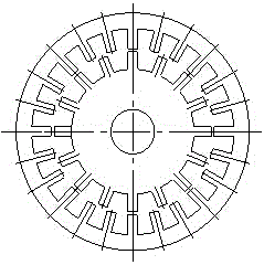
The invention discloses a magnetic-resistance type toothless elevator traction machine which comprises a spindle. A traction sheave is connected on the spindle, a detachable handwheel is arranged beside the traction sheave, an electro-magnetic drum brake is connected to the other end of a shaft where the detachable handwheel is located, the lower end of the electro-magnetic drum brake is fixedly connected on a bed, one end of the bed is connected with a front end cover which is connected with an aligning bearing and a rear bearing outer cover respectively, two sides of the front end cover are respectively connected with a front bearing outer cover and a front bearing inner cover, a winding stator core is arranged in the bed, a rotor core is arranged in the inner cavity of the winding stator core, the other end of the bed is connected with a rear end cover which is connected with a deep groove ball bearing and the rear bearing outer cover respectively, and a position sensor is arranged at the tail end of the spindle. By the arrangement, adverse influence brought to a switched reluctance motor by a doubly salient structure is effectively weakened or removed, vibration and noise of the switched reluctance motor are decreased, and stability of operation is improved.

Description

[0001] technical field [0002] The invention belongs to the technical field of switched reluctance motors, in particular to a reluctance type toothless elevator traction machine. Background technique [0003] The driving motor of the elevator traction machine was originally a DC motor. Due to its reversing device, complex structure, reversing electric sparks, and inconvenient maintenance, it has been gradually eliminated in the 1980s. Then the traditional three-phase AC asynchronous single-speed, multi-speed and variable frequency motors are used, and a reducer is equipped to increase the driving torque. The structure of the traction machine is complicated, the transmission efficiency is low, the maintenance cost is high, and the reducer still has leakage. Oil also causes environmental pollution. For this reason, since the end of the 1990s, AC permanent magnet synchronous gearless elevator traction machines have been used at home and abroad to replace the elevator tractio...

Claims


Application Information

Patent Timeline
Patent Type & Authority Applications(China)
IPC IPC(8): B66B11/04
Inventor 任寿萱
Owner SUZHOU FORTUNE TECH DEV
Why Eureka
Try Eureka