
Non-contact laser surface displacement monitoring device with tilt correction function

A tilt correction and non-contact technology, which is applied in the direction of measuring devices, optical devices, instruments, etc., can solve the problems of laser range-finding surface displacement monitoring devices that cannot be used, aggravate laser beam scattering, and large measurement errors, etc., to achieve automatic Correction and self-checking function, high reliability, sufficient observation effect

Inactive Publication Date: 2014-11-12
CHONGQING INST OF GEOLOGY & MINERAL RESOURCES
View PDF6 Cites 13 Cited by
  • Summary
  • Abstract
  • Description
  • Claims
  • Application Information

AI Technical Summary

Problems solved by technology

At present, the common automatic monitoring equipment for displacement includes GNSS, measuring robot, etc. The high purchase price of the above-mentioned monitoring equipment is not conducive to widespread promotion. Therefore, a laser ranging type surface displacement monitoring equipment is proposed.
[0003] However, due to the influence of the processing technology, the sensor used to sense the position of the laser point can only reach a maximum range of 20×20mm 2 , such a small range cannot meet the needs of conventional engineering deformation monitoring
[0004] When the laser source is tilted (the inclination angle is i), the spot of the laser beam on the position sensor will be greatly shifted, resulting in a large measurement error (even gross error). At the same time, the distance between the laser source and the position sensor (S ) is larger, the more obvious the spot shift
According to the theory of small angle measurement: when S=50m, i=0.1°, the spot position offset is 87.27mm, i=0.01°, the spot position offset is 8.73mm), it can be seen that no correction measures are taken for laser ranging type surface displacement Monitoring devices will not be available
[0005] In addition, in order to meet the requirements of low power consumption for long-term monitoring in the field, it is necessary to have the power consumption control function of the laser source; in order to reduce the intensity of ambient light (sunlight) and aggravate the scattering of the laser beam, which will cause the effect of reducing the resolution of the displacement of the position sensor, there are Necessary to design beam function

Method used


Image

  • Non-contact laser surface displacement monitoring device with tilt correction function
  • Non-contact laser surface displacement monitoring device with tilt correction function

Examples


Embodiment Construction

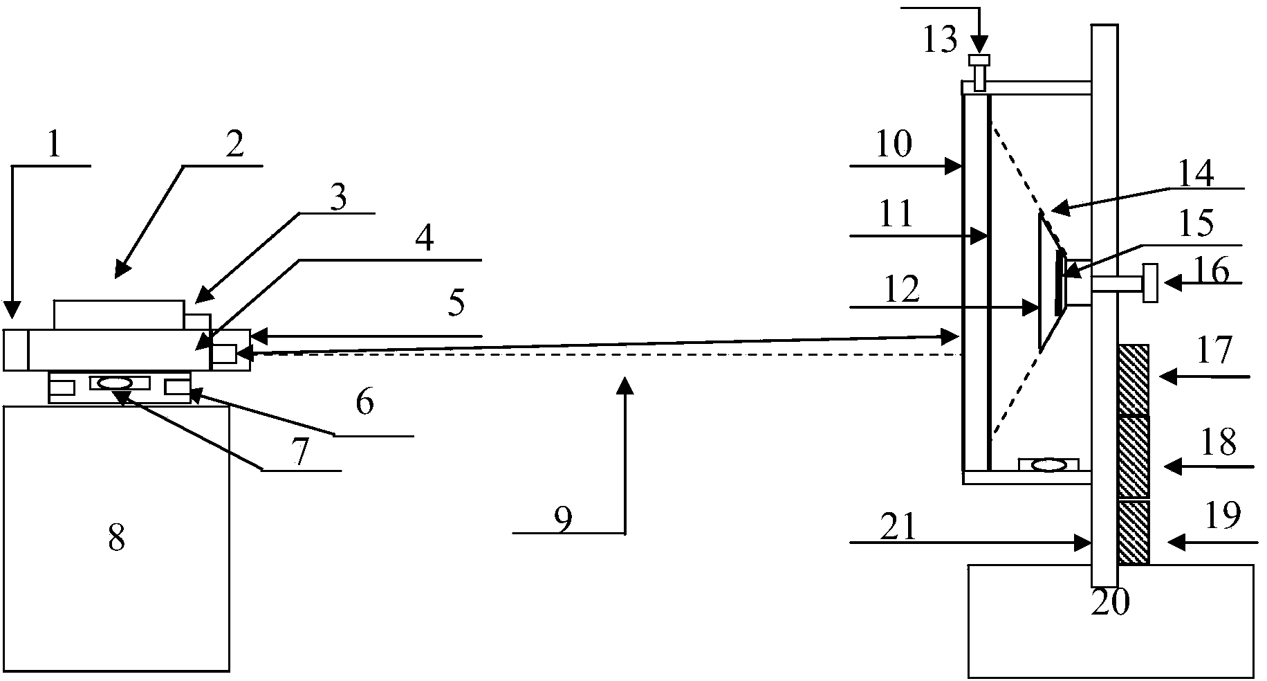
[0017] The specific implementation of the non-contact laser surface displacement monitoring device with tilt correction provided by the present invention will be described in detail below with reference to the accompanying drawings.

[0018] Such as figure 1 As shown, the non-contact laser surface displacement monitoring device with tilt correction includes a laser transceiver terminal, a laser reflection terminal, a corresponding communication module, and host computer software. The laser transceiver terminal is responsible for laser emission and return signal reception to obtain reference points and monitoring points. The laser reflection end is responsible for the laser emission to identify the spot position; the communication module is responsible for the remote communication function of on-site monitoring data; the upper computer software is responsible for monitoring data collection and analysis.

[0019] The installation of the monitoring device is divided into two parts: the...


PUM


Abstract

The invention provides a non-contact laser surface displacement monitoring device with a tilt correction function. The device is characterized in that the monitoring device comprises a laser receiving and emitting end, a laser reflecting end, a corresponding communication module and upper computer software, wherein the laser receiving and emitting end comprises a radio frequency module, a double-axis tilt angle sensor, a temperature sensor, a laser range finder, a laser beam device and a mapping base, the laser reflecting end comprises a two-dimensional PSD displacement sensor, auxiliary parts of the two-dimensional PSD displacement sensor, an installation support, a range adjusting knob, a driving control circuit and a wireless communication module, the communication module is used for remote communication of field monitoring data, and the upper computer software is used for acquisition and analysis of monitoring data. The device has the advantages that automatic monitoring of plane displacement and vertical displacement of deformable bodies can be achieved at the same time, redundant observation quantity is sufficient, self-correction and self-inspection of monitoring data can be achieved, and the reliability of monitoring results is high.

Description

Technical field [0001] The invention belongs to the field of safety early warning, in particular to a non-contact laser ground displacement monitoring device with tilt correction. Background technique [0002] Displacement monitoring has the characteristics of convenient monitoring, intuitive results, and complete early warning theory, which is of great significance in the field of engineering construction or disaster prevention. At present, common automatic monitoring equipment for displacement includes GNSS, measuring robots, etc. The high purchase price of the above monitoring equipment is not conducive to widespread promotion, and therefore a laser ranging type surface displacement monitoring equipment is proposed. [0003] However, the sensor used to sense the position of the laser spot can only reach a maximum range of 20×20mm due to the processing technology. 2 , Such a small range cannot meet the needs of conventional engineering deformation monitoring. [0004] When the las...

Claims


Application Information

Patent Timeline
IPC IPC(8): G01B11/02G01B11/16
Inventor 魏世玉杨建国陈柏林杨富军赵火焱吴孟何飞陈立川姚光华邓涛向强贺建波
Owner CHONGQING INST OF GEOLOGY & MINERAL RESOURCES
Learn More