
Method for manufacturing large bent steel members on basis of fire bending

A manufacturing method and technology of steel components, applied in the direction of manufacturing tools, metal processing, metal processing equipment, etc., can solve problems such as pipeline difficulty, hidden dangers in construction, and high requirements for equipment, and achieve the goals of speeding up the construction period, saving construction costs, and simplifying construction procedures. Effect

Active Publication Date: 2014-11-12
CHINA NAT CHEM ENG THIRD CONSTR
View PDF7 Cites 5 Cited by
  • Summary
  • Abstract
  • Description
  • Claims
  • Application Information

AI Technical Summary

Problems solved by technology

This method protects the performance of the base material of the steel pipe while achieving the purpose of bending. However, this method uses two sets of medium-frequency induction heating systems, hydraulic jacks, infrared temperature measuring instruments and other equipment, and the requirements for the equipment are too high; and the heating temperature is at Between 800°C and 900°C, the nozzle of the pipe is also heated and deformed, which brings difficulty and construction hidden dangers to the subsequent butt welding of the pipe; during the heating process, the pipe relies on a hydraulic jack to provide external force to make the pipe Deformation, due to uneven stress, it is difficult to obtain the target pipeline radian, which is not beautiful but also brings inconvenience to construction, and further improvement is needed

Method used


Image

  • Method for manufacturing large bent steel members on basis of fire bending
  • Method for manufacturing large bent steel members on basis of fire bending
  • Method for manufacturing large bent steel members on basis of fire bending

Examples


Embodiment 1

[0042] There are two methods for making the bends required to bend large steel members: cold bends and hot bends. Due to factors such as the volume of large-scale steel components and the use of machinery, most of them use the hot-simmer bending process, and the hot-simmer bending process is also subdivided into several types: using large-caliber intermediate-frequency bending machine bending, heating first and then extrusion bending Pipe, partial bending and extrusion molding, and then overall welding elbow, etc. Although the existing thermal bending technology can achieve the purpose of bending large steel components, the disadvantages are also very obvious: it is necessary to use large equipment, such as: intermediate frequency bending machine, hydraulic jack, infrared temperature measuring instrument, etc. . It is worth noting that many construction areas are very remote. These large-scale equipment are either difficult to transport or the transportation cost is high, whi...


PUM

PropertyMeasurementUnit
lengthaaaaaaaaaa

Abstract

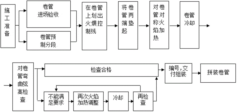
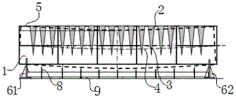
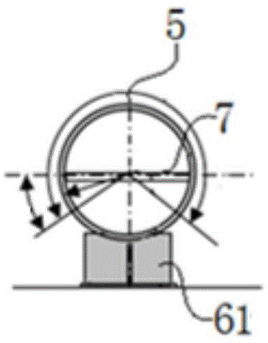
The invention discloses a method for manufacturing large bent steel members on the basis of fire bending and belongs to the technical field of pipeline machining. The method comprises the step of construction preparation, wherein quality detection and algorithm quantification are carried out on reel pipes; the step of reel pipe marking, wherein the reel pipes are supported by a reel pipe supporting device, and heating areas are marked on the reel pipes; the step of fire bending, the heating areas marked well are bent along the zigzag path, and the time duration for bending is decided according to colors generated when the reel pipes are heated; the step of cooling detection, wherein after the reel pipes are cooled, whether the distance between the lower bottoms of the bent reel pipes and the upper end of a detection board is within 3 mm or not is detected, and the reel pipes are qualified if the distance is within 3 mm; the step of secondary processing, wherein when deviation between the actual reel pipe bending chord height H1 and the theoretical reel pipe bending chord height H is large, adjustment is carried out through a gas welding baking handle; the step of reel pipe splicing, wherein the reel pipes reaching the bending standard are welded through a structural steel platform. The method solves the problem that a large instrument is needed when the large bent steel members are manufactured, and no external force needs to be applied.

Description

technical field [0001] The invention relates to the technical field of pipeline processing, more specifically, to a method for manufacturing curved large steel components based on flame bending. Background technique [0002] In some large-scale construction projects, it is necessary to use curved large-scale steel members. The curved large-scale steel members are composed of curved pipes. Among them, the curved pipe is an important connecting member. Its main functions are as follows: one is structural mechanics, two It is to change the direction of the pipeline. The elbow can buffer the tension, pressure and torque added to the straight pipe by the external environment such as stratum migration, earthquake and temperature change where the pipeline is located. Therefore, the performance of the elbow directly affects the quality of the project and the quality of pipeline transportation. Reliability, safety and economy, so the processing technology of the bent pipe is particul...

Claims


Application Information

Patent Timeline
Patent Type & Authority Applications(China)
IPC IPC(8): B21D7/00B21D7/16B21C51/00
Inventor 苏传才马运广
Owner CHINA NAT CHEM ENG THIRD CONSTR
Learn More