
Microwave broadband decoupled network based on signal interference concept

A technology of signal interference and decoupling network, applied in the direction of antenna coupling, etc., can solve the problems of difficult application of broadband antenna, narrow decoupling bandwidth, and no corresponding explanation for the influence of radiation pattern, so as to improve the radiation pattern Effect

Inactive Publication Date: 2014-11-05
NANJING UNIV OF SCI & TECH
View PDF4 Cites 11 Cited by
  • Summary
  • Abstract
  • Description
  • Claims
  • Application Information

AI Technical Summary

Problems solved by technology

The limitation of the first form is that the coupling antenna needs to be fine-tuned to meet the design specifications
For the second one, complex structures need to be designed on the ground plane
The disadvantage of lumped decoupling networks is their relatively narrow decoupling bandwidth due to the frequency-dependent nature of lumped elements
[0004] It can be seen from the above that the implementation methods of the prior art are difficult to apply to broadband antennas, and no corresponding explanation is given for the impact on the radiation pattern

Method used


Image

  • Microwave broadband decoupled network based on signal interference concept
  • Microwave broadband decoupled network based on signal interference concept
  • Microwave broadband decoupled network based on signal interference concept

Examples


Embodiment 1

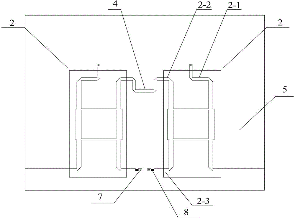
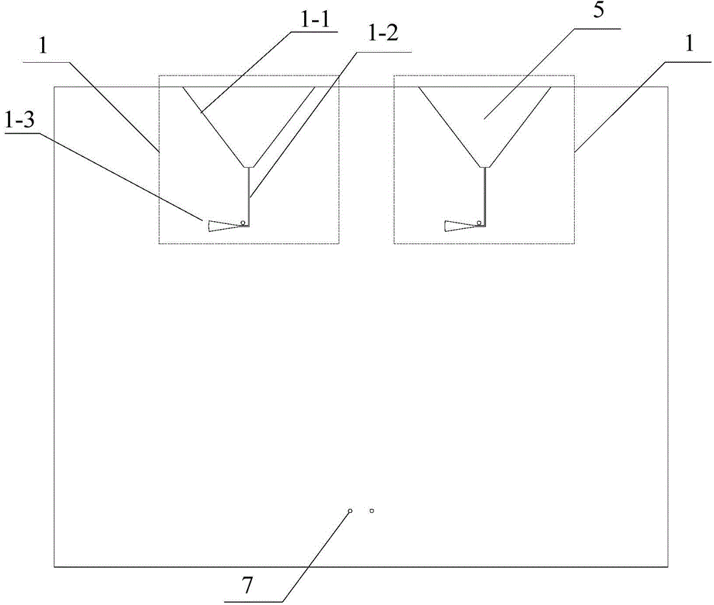
[0028] The complete circuit board size is 130mm×101.7mm; the slot line width of the antenna part is 0.2mm, and the length is 12.5mm. In order to obtain better matching within the working frequency band, the open end of the slot line is designed in the shape of a planar horn, which can make the input impedance of the antenna transition smoothly. The maximum distance between the speaker openings is 28mm, and the minimum distance is 2mm. The short-circuit end of the slot line is designed as a sector, and an ideal energy transition can be obtained by adjusting the arc and radius of the sector. The sector arc is 10 degrees and the radius is 6.5mm. The circuit structure of the coupler part is a traditional branch line directional coupler plus a quarter-wavelength transmission line. The traditional branch line forms a zigzag structure. The length and width of the longitudinal microstrip line are 17.8mm and 3.28mm, respectively, and the transverse The length and width of the strip l...


PUM


Abstract

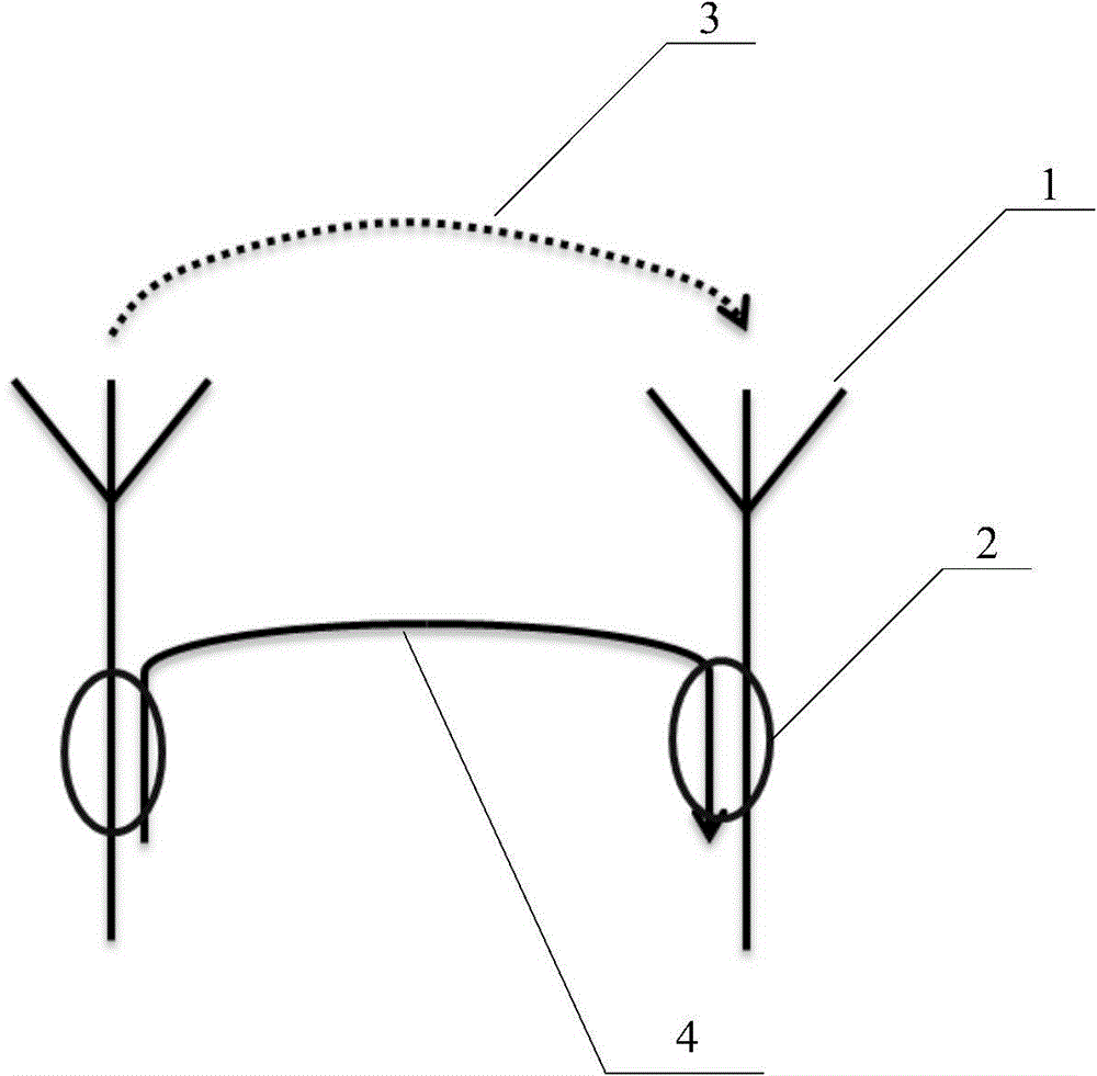
The invention provides a microwave broadband decoupled network based on a signal interference concept. According to the structure, removal of mutual coupling between coupled antennas serves as a design starting point, according to a signal interference method, two same broadband directional couplers are connected to serve as a guide-in path, mutual coupling energy of the antennas and energy of the guide-in path generate voltage zero points on a connecting line and then are offset, and therefore the broadband decoupled network is obtained. The decoupled network is of a plane micro-strip structure, and a dielectric slab is made of FR4. With the cooperation of thin film chip resistors, the structure is simple, machining is easy, cost and weight are low, and therefore large-scale production can be achieved. A novel technical scheme is provided for front end design of a broadband receiving and transmitting system, and the combination modes of microwave passive circuits are increased.

Description

technical field [0001] The invention relates to a microwave planar circuit for removing mutual coupling between antenna arrays placed in close distance, in particular to a coupler-based microwave broadband decoupling network. Background technique [0002] Advances in next-generation communication systems have created an urgent need for portable and compact terminals with channel capacity and throughput. In order to improve the channel capacity of the communication system, according to Shannon's theorem, one method is to widen the system bandwidth, which is applied to the third-generation mobile phones; another method is to use multiple-input multiple-output (MIMO) technology. Both ends use multiple antennas to increase channel capacity. Therefore, future high-capacity mobile terminals require compact broadband multi-antenna systems. For portable terminals, multiple antennas should be placed in a small space, so the distance between the antennas is much smaller than half a ...

Claims


Application Information

Patent Timeline
Patent Type & Authority Applications(China)
IPC IPC(8): H01Q1/52
Inventor 车文荃史苏阳陈海东冯文杰江涛
Owner NANJING UNIV OF SCI & TECH
Learn More