
Laser scanning type bulk material flow detection and distribution error elimination method

A technology of laser scanning and error elimination, applied in the direction of measuring flow/mass flow, liquid/fluid solid measurement, measuring devices, etc., to achieve the effect of high degree of automation, simple structure, and strong real-time performance

Active Publication Date: 2014-11-05
WUHAN ZHONGYUAN ELECTRONICS GRP
View PDF6 Cites 52 Cited by
  • Summary
  • Abstract
  • Description
  • Claims
  • Application Information

AI Technical Summary

Problems solved by technology

At present, there is only research on the nonlinear measurement error of the distribution of the measured material of the radioactive instrument, see the literature "④" (④ Wang Junliang, Zhang Xinguo, Ma Yide. Research on the nonlinear measurement error of the measured material distribution of the radioactive instrument [J]. Gansu Science Journal, 1999, 11(3): 44-47.) There is no research on the measurement method for the instantaneous flow distribution error of laser detection materials. Therefore, it is necessary to explore a high-precision real-time online belt conveyor material flow distribution that is not affected by operating conditions. The error elimination method and its application in the laser scanning bulk material instantaneous flow detection system will have strong practical value

Method used


Image

  • Laser scanning type bulk material flow detection and distribution error elimination method
  • Laser scanning type bulk material flow detection and distribution error elimination method
  • Laser scanning type bulk material flow detection and distribution error elimination method

Examples


Embodiment Construction

[0036] Below in conjunction with embodiment the present invention is described in further detail.

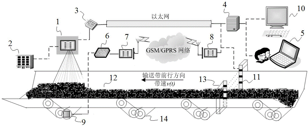
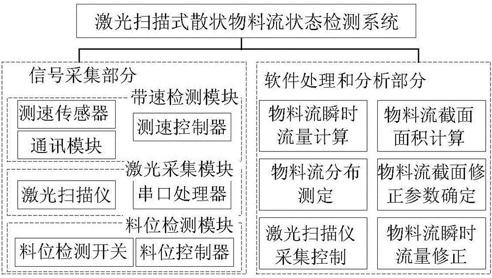
[0037] A laser scanning type bulk material flow detection and distribution error elimination system, the system includes a host computer, the host computer includes a material flow section profile detection module, a material level detection module, a belt speed detection module and a material distribution state measurement module.

[0038] The material flow cross-sectional profile detection module is provided by the material level detection module to collect the start signal, and the two-dimensional laser scanner is used to detect in real time the cross-sectional profile of the material flow through the laser scanning sector during the forward process of the conveyor belt, realizing the three-dimensional material flow profile of the belt conveyor Real-time acquisition of laser point cloud data.

[0039] The material level detection module is installed at a certain position away...


PUM


Abstract

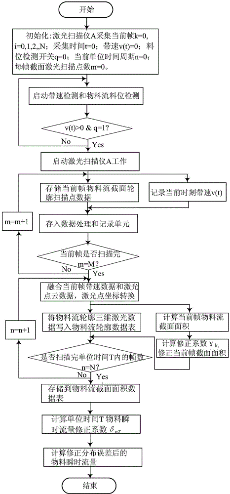
The invention discloses a laser scanning type bulk material flow detection and distribution error elimination method. Collecting point data and belt speed data of frames of section contours of a material stream are obtained; three-dimensional coordinates are built according to collecting point data and belt speed data; the material flow between adjacent frames is obtained through a triangulation network construction method, and the instantaneous flow rate of a unit time is obtained; the material stream sectional area is worked out by calculating the area difference between a material and a no-load belt scanned by a laser scanner, the area R defined by the straight line where the starting angle of each frame scanned by the laser scanner is located, the straight line where the termination angle of the frame scanned by the laser scanner is located and the corresponding material stream section contour in the material conveying process is calculated, and the material stream sectional area of each frame is obtained; the sectional area distribution error correction factor of the kth frame of the material stream is obtained; the corrected material stream sectional area is calculated. The laser scanning type bulk material flow detection and distribution error elimination method is simple in structure, high in automation degree and high in real time performance, and material distribution measurement is not influenced by dust, the weather, light and the like in the external environment.

Description

technical field [0001] The invention relates to the field of on-line detection of materials, in particular to a laser scanning type bulk material flow detection and distribution error elimination method, which is suitable for detection of transmission material parameters. Background technique [0002] In the field of continuous conveying of bulk materials such as coal mines, metal mines, cement and grain, the operating status of materials needs to be strictly and effectively monitored, otherwise it will easily affect the normal operation of the belt conveyor system, and even lead to damage to system components and a decrease in system operating efficiency. resulting in huge economic losses. If the material is prone to local aggregation at the drop point, this phenomenon will directly lead to wear or tear of the conveyor belt. In addition, when the materials on the conveyor belt of the belt conveyor system are unevenly distributed or the load is light, almost 40% of the syst...

Claims


Application Information

Patent Timeline
IPC IPC(8): G01F1/74G01F25/00
Inventor 吴青张东华初秀民陈鹏陈伟任学锋曾飞梁跃虹许晶王媛
Owner WUHAN ZHONGYUAN ELECTRONICS GRP
Learn More