
Lightening current drainage stripe and manufacturing method thereof

A technology of drainage strip and lightning, applied in the field of lightning drainage strip and its production, can solve the problems of many exposed parts of metal sheets, troublesome arrangement of metal sheets, low processing efficiency, etc., so as to reduce the difficulty of processing and operation, and improve the processing efficiency. And the degree of neatness, the effect of improving product life

Inactive Publication Date: 2014-10-15
范晓宇
View PDF8 Cites 3 Cited by
  • Summary
  • Abstract
  • Description
  • Claims
  • Application Information

AI Technical Summary

Problems solved by technology

In view of the existing domestic processing conditions, especially in small batch production, this method also has defects such as difficult processing and high cost, and there are many exposed parts of the metal sheet, which are easy to fall off
Chinese Patent No. [ZL201210041392.7] discloses a fragmented drainage strip and its manufacturing method, in which the metal sheet of the drainage strip is cut separately and pasted on the insulating base tape with a template. This method has the following defects: a separate metal The arrangement of the pieces is very troublesome and the processing efficiency is low. It is more troublesome to spray aluminum powder on the glue layer between the pieces. In addition, the entire upper surface of the metal piece is exposed, and there is a possibility of falling off.

Method used


Image

  • Lightening current drainage stripe and manufacturing method thereof
  • Lightening current drainage stripe and manufacturing method thereof
  • Lightening current drainage stripe and manufacturing method thereof

Examples


Embodiment Construction

[0036] The present invention will be described in further detail below in conjunction with the accompanying drawings and embodiments.

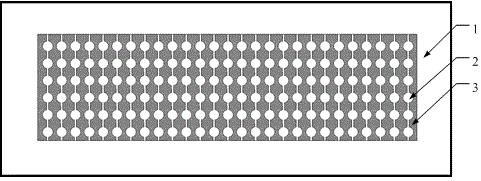
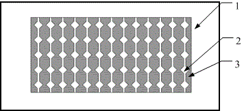
[0037] see image 3 , 4 , 5, a lightning drainage strip, including a drainage strip body 8, a plurality of groups of metal sheets 2 are distributed on the strip 4 of the drainage strip body 8, and insulating medium 3 is filled around the metal sheet 2, and the insulating medium 3 can be made of aluminum Powdered adhesive, the insulating base tape 6 is provided with a double-sided tape 7. The metal thin plate 1 is an aluminum plate or a stainless steel plate with a thickness of 0.1-0.5mm, and the length and width are determined according to actual needs. Figure 4 and Figure 5 An example of a lightning current strip made as described below. see figure 1 , figure 2 , on the thin metal plate 1, the shape of the transverse connection of the metal sheets 2 is cut out by laser cutting or other means. figure 1 The metal sheet is round in sha...


PUM


Abstract

Disclosed is a lightening current drainage stripe. According to the lightening current drainage stripe, the stripe-shaped current drainage stripe body is provided with a plurality of groups of metal pieces, insulating mediums are filled around the metal pieces, both sides of every metal piece are covered by thin bonder layers, and the back surface of an insulating base stripe is provided with double-faced adhesive tapes. The manufacturing method of the lightening current drainage stripe comprises the steps of 1) manufacturing a polyester film into a long stripe serving as the insulating base stripe; 2) laser-cutting or wire-cutting out the metal pieces with both sides connected from a metal sheet; 3) filling bonders containing metal powder into the cut-out portions of the metal sheet; 4) after the bonders solidify, cutting the metal sheet into stripes, wherein every stripe comprises a plurality of groups of the metal pieces, and the metal pieces are connected through the bonders; 5) adhering the stripes onto the insulating base strip; 6) applying bonders on both sides of the stripes, cover both sides of the metal pieces through the bonder layers and exposing the round portions or the diamond-shaped portions in the middles of the metal pieces; 7) fixing the metal pieces onto the insulating base stripe through solidification of the bonders; 8) adhering the double-faced adhesive tapes onto the back surface of the base strip. The lightening current drainage stripe is good in protecting effects, long in service life, simple in structure and easy to machine and operate.

Description

technical field [0001] The invention belongs to the technical field of lightning protection, and in particular relates to a lightning drainage bar and a manufacturing method thereof. The lightning diversion strip can be used for lightning protection of blades of wind power generators, and can also be applied to aircraft components and radar radomes. Background technique [0002] Wind turbines are often located in areas of severe lightning strikes, installed higher than the surrounding area and away from other high objects, they are more vulnerable to lightning strikes. And the huge wind blades of modern wind turbines are usually made of composite materials. The blades made of these materials are easily damaged by lightning because these materials have poor electrical conductivity. Therefore, it is very necessary to take lightning protection measures for wind blades. Aircraft are vulnerable to lightning strikes during flight, and the high voltage and high current during lig...

Claims


Application Information

Patent Timeline
IPC IPC(8): H01Q1/50H01Q1/42F03D11/00B64D45/02
CPCY02E10/722Y02P70/50
Inventor 范晓宇
Owner 范晓宇
Learn More