
Tool sharpener

A knife sharpening machine and knife sharpening stand technology, which is applied in the direction of grinding workpiece brackets, other manufacturing equipment/tools, manufacturing tools, etc., can solve the problems of consistency and manufacturing efficiency, and achieve small assembly errors and consistent molding Good performance and high production efficiency

Inactive Publication Date: 2014-10-01
范昕昀
View PDF8 Cites 3 Cited by
  • Summary
  • Abstract
  • Description
  • Claims
  • Application Information

AI Technical Summary

Problems solved by technology

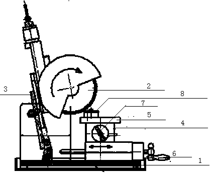
[0006] Aiming at the problem that consistency and manufacturing efficiency cannot be taken into account in the current blade manufacturing, the present invention provides a sharpening machine, which includes a chassis, a sharpening wheel, a grinding wheel frame, and a sharpening frame assembly, and the grinding wheel frame is fixed on the Chassis, the grinding wheel frame is provided with a card slot, and the grinding wheel is fixed to the wheel frame along the card slot. The tool grinding frame assembly includes a bracket, a rotating shaft frame, and an in-out knife adjustment handle and a positioning tool for adjusting the position of the bracket. Adjusting the handle, the sharpening frame assembly also includes a rotating sharpening frame mold, and the rotating sharpening frame mold includes a diamond-shaped clamp body

Method used


Image

  • Tool sharpener
  • Tool sharpener

Examples


Embodiment 1

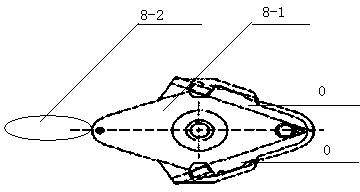
[0019] Such as figure 1 As shown, a knife sharpening machine includes a chassis 1, a sharpening wheel 2, a grinding wheel frame 3, and a knife sharpening frame assembly. The grinding wheel frame 3 is fixed to the chassis 1 through a hinge, and the grinding wheel frame 3 is provided with a slot , the sharpening wheel 2 is fixed on the grinding wheel frame 3 along the slot, and the sharpening frame assembly includes a bracket 4, a rotating shaft frame 5, and an in-out knife adjustment handle 6 and a positioning adjustment handle 7 for adjusting the position of the bracket 4. The sharpening frame assembly also includes a rotary sharpening frame mold 8, and the rotary sharpening frame mold 8 includes a diamond-shaped clamp body 8-1. Rhombus clamp body 8-1 tail end is also fixed with handle 8-2, as figure 2 shown in . Fix the two blades 0 respectively on the adjacent sides of the rhombic fixture body 8-1, and fix and tighten them through bolts and screw holes.

[0020] Adjust t...


PUM


Abstract

The invention relates to a tool sharpener, in particular to a tool sharpener capable of machining two tools at the same time. The tool sharpener aims to solve the problem that according to an existing blade manufacturing technology, consistency and manufacturing efficiency cannot be considered at the same time. The tool sharpener comprises a base plate, a tool sharpening grinding wheel, a grinding wheel frame and a tool sharpening frame assembly. The grinding wheel frame is fixed to the base plate through a hinge. A clamping groove is formed in the grinding wheel frame. The tool sharpening grinding wheel is fixed to the grinding wheel frame along the clamping groove. The tool sharpening frame assembly comprises a supporting frame, a rotating shaft frame, a tool feeding and discharging adjusting handle and a locating adjusting handle, wherein the tool feeding and discharging adjusting handle and the locating adjusting handle are used for adjusting the position of the supporting frame. The tool sharpening frame assembly further comprises a rotating tool sharpening frame die. The rotating tool sharpening frame die comprises a rhombic clamp body. The blade manufactured through the tool sharpener is small in assembly error and good in forming consistency. Besides, two blades can be manufactured at the same time, and therefore the production efficiency is high.

Description

technical field [0001] The invention relates to a knife sharpening machine, in particular to a knife sharpening machine capable of processing two knives at the same time. [0002] Background technique [0003] The sharpening machines currently on the market can only process one knife at the same time. If you need a field with a very high consistency of the knife itself, you need to constantly adjust the position of the grinding wheel to use the existing knife sharpening machine. Not only is the operation very complicated and difficult to control, but also because it takes a lot of time to calibrate, it seriously affects the manufacturing efficiency. [0004] In the field of scalpel manufacturing, this problem is particularly prominent because the scalpel has very high requirements for the consistency of the blade. [0005] Contents of the invention [0006] Aiming at the problem that consistency and manufacturing efficiency cannot be taken into account in the current bl...

Claims


Application Information

Patent Timeline
Patent Type & Authority Applications(China)
IPC IPC(8): B24B3/36
CPCB24B3/36B24B41/06
Inventor 范昕昀
Owner 范昕昀
Learn More