
Pipeline piece resistance butt welding method

A technology for resistance butt welding and pipe fittings, which is used in resistance welding equipment, welding media, pressure electrodes, etc.

Active Publication Date: 2014-09-24
OCEAN UNIV OF CHINA +1
View PDF6 Cites 8 Cited by
  • Summary
  • Abstract
  • Description
  • Claims
  • Application Information

AI Technical Summary

Problems solved by technology

At present, there is no simple and effective method to achieve effective control and realize resistance butt welding between dissimilar metals.

Method used


Image

  • Pipeline piece resistance butt welding method
  • Pipeline piece resistance butt welding method
  • Pipeline piece resistance butt welding method

Examples


Embodiment 1

[0023] The first step is to select two pipeline parts to be welded, which are copper tubes and aluminum tubes. The resistivity of copper is about 16.73 (nΩ·m), and the resistivity of aluminum is about 26.55 (nΩ·m). The welded end of the copper tube is necked.

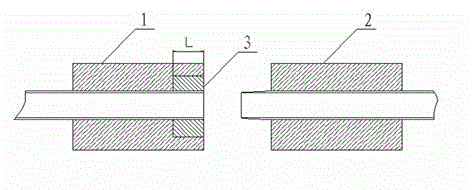
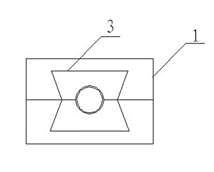
[0024] The second step is to make electrodes, such as figure 1 , 2 As shown, the welding equipment is selected. The welding equipment is provided with clamp electrodes. The clamp electrodes include a first electrode 1 and a second electrode 2. Both the first electrode 1 and the second electrode 2 are composed of upper and lower clamp electrodes. The upper and lower clamping electrodes of the electrode 1 and the second electrode 2 are provided with a groove with a semicircular cross section, so that the first electrode 1 and the second electrode 2 form a central hole after assembly, and the aluminum tube and the copper tube are respectively fixed on the In the center hole of the first electrode 1 and the second electro...

Embodiment 2

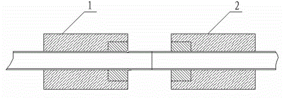
[0034] In this embodiment, aluminum tube-aluminum tube butt welding is selected. Such as image 3 As shown, in order to prevent the aluminum tube from destabilizing at high temperature, an auxiliary electrode 3 is provided on both the first electrode 1 and the second electrode 2. The assembly structure of the auxiliary electrode is the same as that of the auxiliary electrode on the first electrode 1 in Example 1. The aluminum pipes to be welded are respectively installed on the first electrode 1 and the second electrode 2, and then are butt welded. Due to the low melting point of the aluminum tube, brass can be selected to make the auxiliary electrode, and the coefficient n is 0.5.

Embodiment 3

[0036] When the pipeline parts are aluminum tube-304 stainless steel tube, the resistivity of the aluminum tube is 26.55 (nΩ·m), and the resistivity of the 304 stainless steel tube is 73 (nΩ·m). On the electrode side, the aluminum tube is placed on the second electrode side, and the end of the aluminum tube is shrunk, and the rest are the same as in Embodiment 1.


PUM

PropertyMeasurementUnit
electrical resistivityaaaaaaaaaa

Abstract

The invention relates to a pipeline piece resistance butt welding method, solves the technical problem of providing a pipeline piece resistance butt welding method, and achieves the aim of controlling the welding temperature of metal pipeline pieces. The method adopts the technical scheme that the resistance butt welding method for changing the resistance heat of metal to be welded comprises the following steps: firstly, selecting a welded pipe, secondly, manufacturing electrodes, thirdly, fixing a pipeline piece, and fourthly, performing welding, starting welding equipment and accomplishing resistance butt welding, wherein the welding equipment comprises a first electrode and a second electrode; the first and second electrodes are provided with central holes for fixing the pipeline; a notch(s) is(are) formed in the welded side(s) of the first electrode and / or the second electrode; an auxiliary electrode is embedded in the notch; the auxiliary electrode is also provided with a central hole for clamping the pipeline piece. The auxiliary electrode has the effect of shunting, and can also absorb the resistance heat of the interior of the pipeline piece and adjust the heat produced in a region to be welded of the pipeline piece.

Description

technical field [0001] The invention relates to a method for resistance butt welding of pipe fittings, in particular to a method for resistance butt welding of pipelines made of dissimilar metal materials. Background technique [0002] Butt resistance welding is a resistance welding method that uses resistance heat to weld two workpieces together along the entire end face at the same time. It is often used for butt joints of wires, rods, pipe materials or ring workpieces. [0003] When two workpieces are resistance butt welded, the two workpieces to be welded are respectively placed in the left and right clamp electrodes, and the end faces of the two workpieces are always pressed tightly. When the current passes through the clamp electrodes and the workpiece to form the secondary circuit of the welding transformer , the current will generate an electric heating group in the workpiece, and the electric heating group will heat the welded part of the workpiece to a plastic stat...

Claims


Application Information

Patent Timeline
Patent Type & Authority Applications(China)
IPC IPC(8): B23K11/02B23K11/30B23K35/04
CPCB23K11/02B23K11/3009B23K35/0205B23K2101/06B23K2103/18
Inventor 赵越万延尧王昕苏颖陈德娟张尚李青溪徐源
Owner OCEAN UNIV OF CHINA
Learn More