
High-temperature superconducting binary current lead based on conduction cooling

A binary current lead and high-temperature superconducting technology, which is applied in the direction of superconducting magnets/coils, circuits, electrical components, etc., can solve the application of limited conduction binary current leads, lead wires cannot be flexibly wired and installed, and internal space is crowded, etc. problems, to achieve the effect of fast heat dissipation, excellent thermal conductivity and electrical insulation performance, and reduce heat load

Inactive Publication Date: 2014-09-17
中国东方电气集团有限公司
View PDF8 Cites 8 Cited by
  • Summary
  • Abstract
  • Description
  • Claims
  • Application Information

AI Technical Summary

Problems solved by technology

[0005] At present, for the conduction-type binary current lead that abandons gas cooling, since most of its superconducting section adopts inflexible design, this lead cannot be flexibly routed and installed inside the vacuum dewar, especially for complex low-temperature environments. Space is already crowded with multiple layers of vacuum insulation
At the same time, due to the cooling of the cold head, the traditional binary current leads involve thermal connection and electrical insulation. In most cases, it is impossible to ensure that both effects are good at the same time.
These problems greatly limit the application of conductive binary current leads in high current and fine low temperature spaces

Method used


Image

  • High-temperature superconducting binary current lead based on conduction cooling
  • High-temperature superconducting binary current lead based on conduction cooling
  • High-temperature superconducting binary current lead based on conduction cooling

Examples


Embodiment Construction

[0025] The present invention will be further described below in conjunction with the accompanying drawings and specific embodiments.

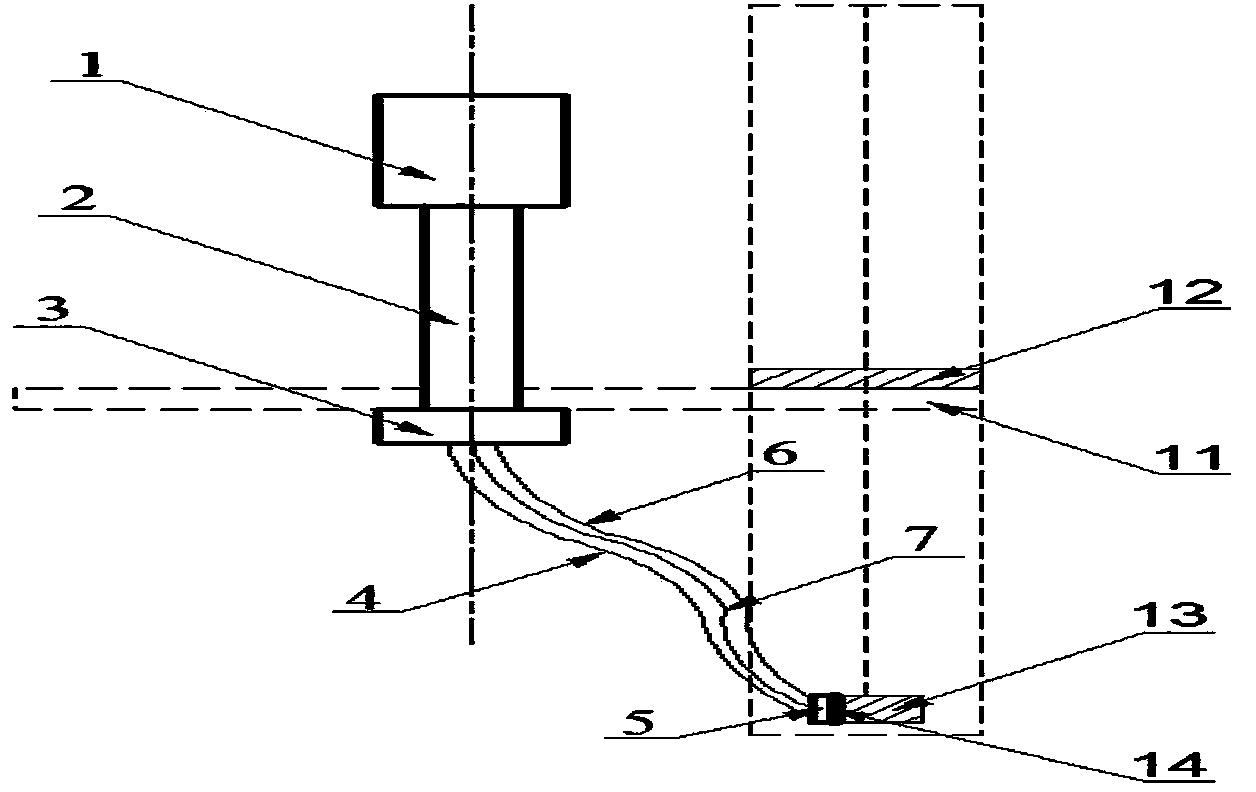
[0026] The high-temperature superconducting binary current leads of this scheme, such as figure 1 As shown, it is composed of room temperature copper joint 1, copper lead section 2, connecting transition section 3, superconducting combination section 4 and low temperature copper joint 5, and its cooling method is realized by conduction cooling of a two-stage refrigerator. combine figure 1 and figure 2 It can be seen that the current lead superconducting combined section 4 is mainly composed of copper braid 6 and superconducting strip 7 .

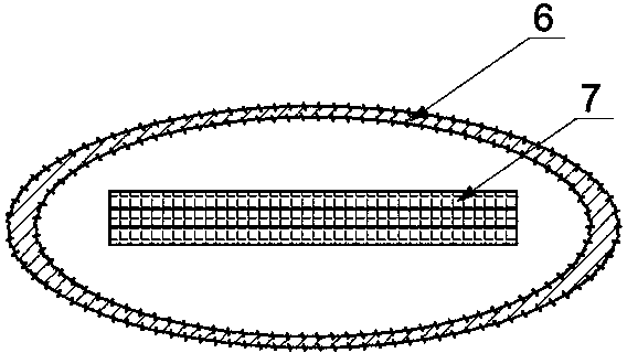
[0027] Such as figure 2 As shown, the superconducting strip 7 is installed inside the copper braid 6, and its quantity can be determined according to the user's current demand.

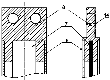
[0028] Such as image 3 As shown, the processing of the upper and lower end joints 8 of the superconducting combined section...


PUM


Abstract

The invention provides a conduction cooling type high-temperature superconducting binary current lead which is simple in process and convenient to install, and particularly relates to a structure of the high-temperature superconducting binary current lead. The whole high-temperature superconducting binary current lead comprises an indoor temperature copper connector, a copper lead section, a connection transition section, a superconducting combination section and a low temperature copper connector, and is characterized in that a two-stage refrigerating machine is adopted for the whole current lead for conduction cooling, the structure is simple, the cooling effect is good, and installation is convenient. Meanwhile, the conduction cooling type high-temperature superconducting binary current lead is wider in application range relative to gas cooling, for example, the conduction cooling type high-temperature superconducting binary current lead can be applied to a superconducting fan. The superconducting combination section of the current lead is formed by welding finished superconducting strips and a copper braided strap, the current lead can be obtained by increasing or decreasing the number of the superconducting strips in parallel connection according to the demands of users for the magnitude of currents, machining and installation processes are simplified, materials are saved, and cost of the lead is saved.

Description

technical field [0001] The invention relates to a high-temperature superconducting current lead, in particular to a high-temperature superconducting binary current lead based on conduction cooling. Background technique [0002] Current leads are used to connect the magnet assembly to the room temperature power supply. The current superconducting magnet device needs to work in a low-temperature environment. Therefore, the heat leakage from room temperature into the low-temperature environment through the current lead is the main heat load of the low-temperature environment, and affects the stability of the low-temperature environment and determines the power consumption for maintaining the low-temperature environment. If the superconducting magnet uses unary copper current leads and uses helium cooling, the design of the entire cooling system is complicated, the cost is high, and the heat leakage to the low temperature environment is relatively large. Under the premise of sa...

Claims


Application Information

Patent Timeline
Patent Type & Authority Applications(China)
IPC IPC(8): H01F6/06H01R4/68
Inventor 任毅张治宇杨烨蒋煜东张敏冯玲况明伟张筱吴建东
Owner 中国东方电气集团有限公司
Learn More