Electric permanent-magnet iron separator

A technology of iron remover and electric permanent magnet, which is applied in the direction of magnetic separation, chemical instruments and methods, solid separation, etc., and can solve the problems of secondary pollution, disappearance and difficulty in adjustment of permanent magnetic iron remover

Inactive Publication Date: 2014-09-17
岳阳鸿升电磁科技有限公司
View PDF10 Cites 1 Cited by
  • Summary
  • Abstract
  • Description
  • Claims
  • Application Information

AI Technical Summary

Problems solved by technology

[0003] Based on this, it is necessary to provide a magnetic field that can also generate a magnetic field during a power failure and solve the problems of the traditional electromagnetic iron remover once the power is cut off, the main body magnetism disappears, the iron-absorbing parts fall off and cause secondary pollution, and the magnetic force of the permanent magnet iron remover is difficult to adjust. Electric permanent magnet iron remover with automatic adjustment of magnetic force

Method used


Image

  • Electric permanent-magnet iron separator
  • Electric permanent-magnet iron separator
  • Electric permanent-magnet iron separator

Examples


Embodiment Construction

[0019] In order to facilitate the understanding of the present invention, the present invention will be described more fully below with reference to the associated drawings. A preferred embodiment of the invention is shown in the drawings. However, the present invention can be embodied in many different forms and is not limited to the embodiments described herein. Rather, these embodiments are provided so that the disclosure of the present invention will be thorough and complete.

[0020] It should be noted that when an element is considered to be “disposed” on another element, it may be directly disposed on the other element or there may be an intervening element at the same time. The terms "bottom", "lateral" and similar expressions are used herein for the purpose of illustration only.

[0021] Unless otherwise defined, all technical and scientific terms used herein have the same meaning as commonly understood by one of ordinary skill in the technical field of the inventio...


PUM


Abstract

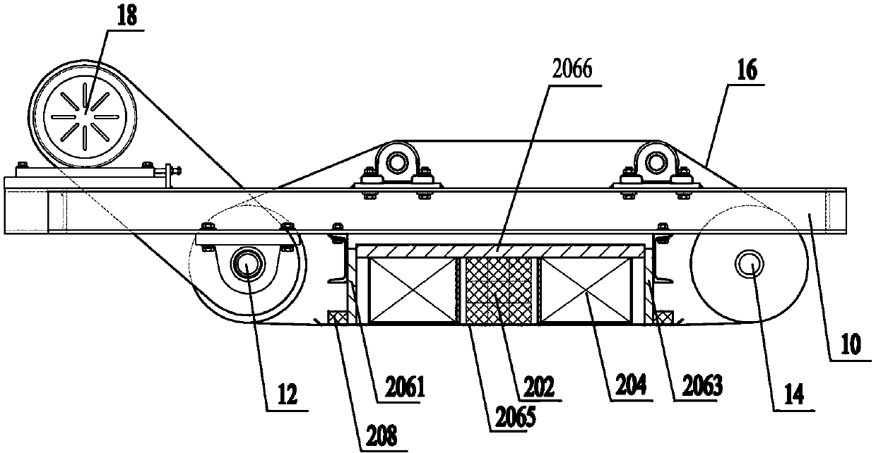
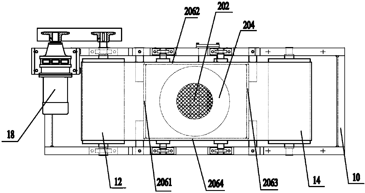
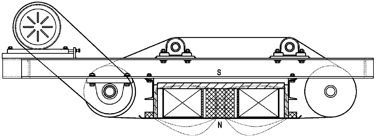
The invention provides an electric permanent-magnet iron separator. The electric permanent-magnet iron separator comprises a rack, a driving belt wheel, a driven belt wheel, an iron separation belt and a magnetic system body, wherein the driving belt wheel and the driven belt wheel are arranged at two ends of the rack; the iron separation belt is wound on the driving belt wheel and the driven belt wheel, and the head and tail ends of the iron separation belt are closed; the magnetic system body is arranged inside the bottom of the iron separation belt and comprises a permanent-magnet source, an electromagnetic coil which is wound on the periphery of the permanent-magnet source, and a magnetic conduction shell which is used for accommodating the permanent-magnet source and the electromagnetic coil; the direction of a magnetic field generated by the permanent-magnet source is parallel to the direction of the magnetic field generated by the electromagnetic coil. According to the electric permanent-magnet iron separator, a basic working magnetic field is generated by the permanent-magnet source, and the magnetic force can be automatically adjusted by virtue of energizing / de-energizing and change of the energizing direction, so that the functions of iron separation through normal excitation, strong excitation, short-time ultra-strong excitation, reversing excitation and the like are realized.

Description

technical field [0001] The invention relates to magnetic separation equipment, in particular to an electric permanent magnet iron remover. Background technique [0002] In the actual production process, various forms of electromagnetic iron remover are used to remove iron from materials. Electromagnetic iron remover is a kind of electromagnetic equipment used to remove iron parts in bulk non-magnetic materials. It is generally installed at the head or middle of the belt conveyor. The strong magnetic force generated by its electrification will pick up the iron parts mixed in the material and throw them out from the unloading belt to achieve the purpose of automatic removal, and can effectively prevent the conveyor belt from being scratched longitudinally and protect the normal operation of crushers and grinders. Work. However, once the power of the traditional electromagnetic iron remover is cut off, the magnetism of the main body will disappear, and the iron-absorbed parts...

Claims


Application Information

Patent Timeline
IPC IPC(8): B03C1/22
Inventor 梁志军王辉曾谷成
Owner 岳阳鸿升电磁科技有限公司
Why Eureka
Try Eureka