
Metal micro-spraying molten drop electromagnetic restraint deposition modeling system

A deposition molding and droplet technology, which is applied in the field of metal micro-spray droplet electromagnetic confinement deposition molding system, can solve the problems that affect the forming accuracy and quality, the difficulty of controlling the droplet flow, and affect the product accuracy and quality, so as to reduce the cost of equipment , Improve molding quality, improve molding accuracy and efficiency

Inactive Publication Date: 2014-09-10
XI AN JIAOTONG UNIV +1
View PDF7 Cites 27 Cited by
  • Summary
  • Abstract
  • Description
  • Claims
  • Application Information

AI Technical Summary

Problems solved by technology

[0004] There have been researches on the droplet deposition molding method, but in terms of metal droplet deposition molding, there are still many problems that affect the forming accuracy and quality to be solved urgently, such as the difficulty of controlling the droplet flow and thermal cracks caused by the concentration of thermal stress between the forming layers. , The gas is sealed during solidification, resulting in air pockets and solidification shrinkage micropores, etc., which will affect the accuracy and quality of the final product. Among them, the precise control of the melt flow and solidification process during the metal droplet deposition and solidification process is to restrict the metal droplet deposition. The bottleneck of the development of forming technology, so the precise control of droplet flow and solidification forming process has become the focus and difficulty of research in metal droplet deposition molding

Method used


Image

  • Metal micro-spraying molten drop electromagnetic restraint deposition modeling system

Examples


Embodiment Construction

[0016] The present invention will be further described in detail below in conjunction with the drawings:

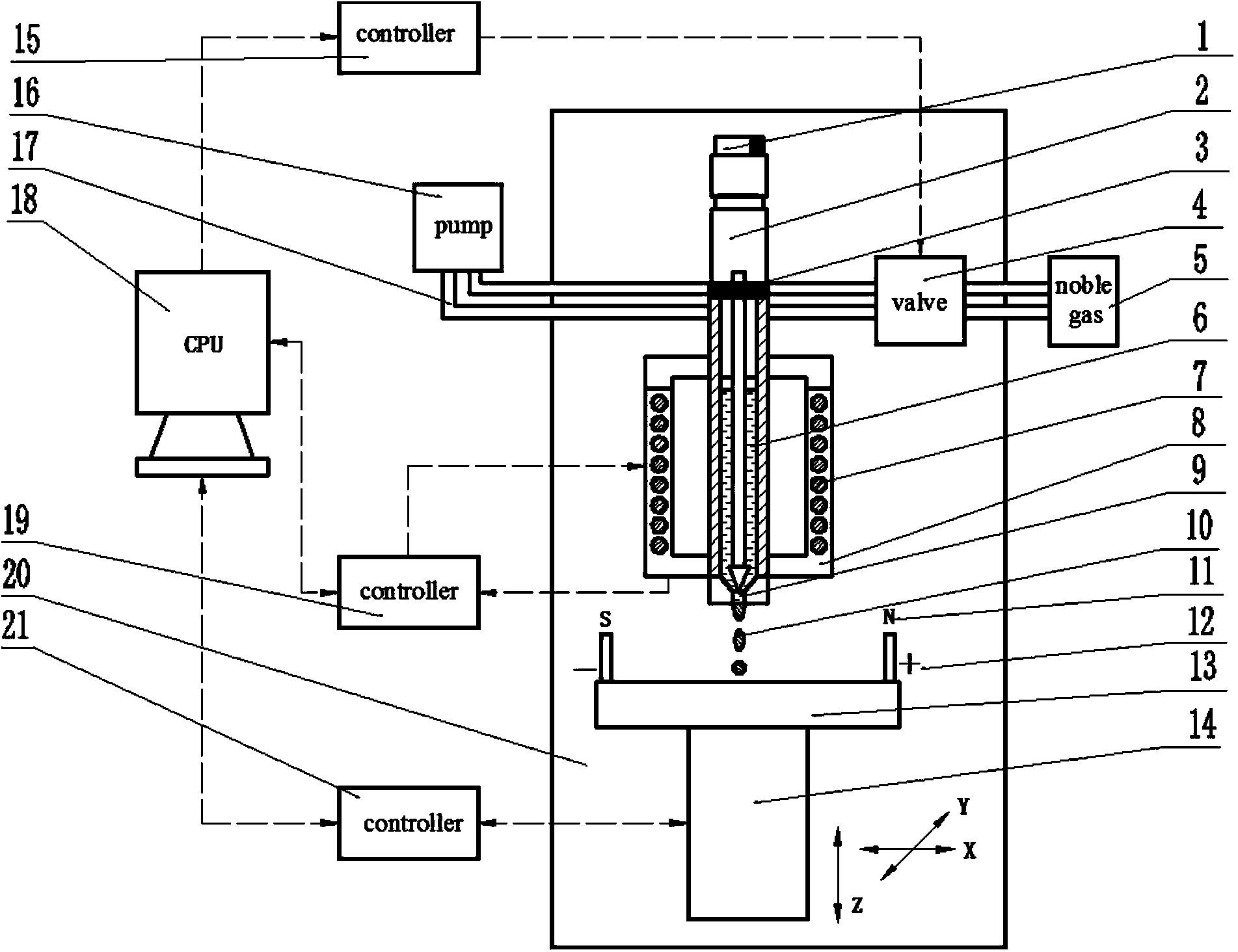
[0017] Such as figure 1 As shown, a metal micro spray droplet electromagnetic confinement deposition molding system of the present invention includes a gap fine-tuning instrument 1, a piezoelectric actuator 2, a piezoelectric valve 4, an inert gas tank 5, a heating element 7, a crucible 8, and an adjustable gap Nozzle 9, alternating magnetic field 11, alternating electric field 12, substrate 13, three-dimensional worktable 14, pressure controller 15, control system 18, temperature controller 19, glove box 20 and motion control card 21.

[0018] Among them, the three-dimensional workbench 14 is arranged at the bottom of the glove box 20, the substrate 13 is located on the upper end surface of the workbench 14, and an alternating magnetic field 11 and an alternating electric field 12 are provided on the substrate 13.

[0019] The crucible 8 for holding the metal solution 6 is loc...


PUM

PropertyMeasurementUnit
Diameteraaaaaaaaaa

Abstract

The invention discloses a metal micro-spraying molten drop electromagnetic restraint deposition modeling system. By using the system, a metal molten drop deposition modeling technology, a micro-spraying technology and a metal solidification modeling theory under effects of an electromagnetic field are integrated, expanded and contracted pulse pressure is generated in a cavity of a crucible by using pressure pulses, metal molten drops are uniformly sprayed controllably through a gap-adjustable nozzle as needed by controlling change of the pulse pressure, and the metal micro molten drops are supplied as needed in a molecule manner by adjusting driving control parameters and relative positions of the gap-adjustable nozzle and a substrate. The metal micro molten drops are subjected to accurate deposition modeling in a shape-controlled and performance-controlled manner after the metal micro molten drops flow and are quickly solidified by a restraint effect of an electromagnetic field in environments of small space, high field intensity and high time and temperature gradient by applying the external electromagnetic field to a position nearby a micro molten drop deposition area. The modeling precision and the modeling efficiency of metal composite components are improved; crystalline grains are refined; the density of a microstructure is improved; and the modeling quality is also improved.

Description

【Technical Field】 [0001] The invention belongs to the field of metal three-dimensional additive manufacturing, and in particular relates to a metal micro spray droplet electromagnetic confinement deposition molding system. 【Background technique】 [0002] Additive manufacturing (also known as 3D printing) is a new type of manufacturing technology developed in the 1980s. Its core idea is to discretize three-dimensional parts in two dimensions to form layered data and accumulate the shaped parts layer by layer. Droplet ejection manufacturing is a type of 3D printing. Using the controllable ejection of metal droplets, the metal droplets can directly form a three-dimensional part of the part. The basic principle is to use the instantaneous pulse pressure generated inside the crucible to make the solution pass through the bottom of the crucible. The nozzle ejects and forms a single-particle metal droplet, and then accurately deposits the droplet to a preset position on the moving subst...

Claims


Application Information

Patent Timeline
IPC IPC(8): B22F3/115
Inventor 杜军魏正英陈祯卢秉恒李素丽
Owner XI AN JIAOTONG UNIV
Learn More