Flow velocity distribution equalizing apparatus

A flow velocity distribution and homogenization technology, applied in the direction of charging system, indirect carbon dioxide emission reduction, combustion method, etc., can solve the problems that the rectifying plate cannot cope, the pressure loss is large, and the catalytic burner has no examples, etc.

Inactive Publication Date: 2014-09-03
KAWASAKI HEAVY IND LTD
View PDF8 Cites 3 Cited by
  • Summary
  • Abstract
  • Description
  • Claims
  • Application Information

AI Technical Summary

Problems solved by technology

[0006] However, in the case of installing a flow path with a long linear distance, a large piping space is required, leading to an increase in size
On the other hand, there are no examples regarding the use of rectifying plates for the homogenization of the flow velocity distribution of catalytic burners
In addition, in the case of using rectifying plates, the pressure loss becomes large, and if the flow velocity distribution upstream of the rectifying plates changes greatly, the rectifying plates as a fixed throttling device (winch り means) cannot cope.

Method used


Image

  • Flow velocity distribution equalizing apparatus
  • Flow velocity distribution equalizing apparatus
  • Flow velocity distribution equalizing apparatus

Examples


Embodiment Construction

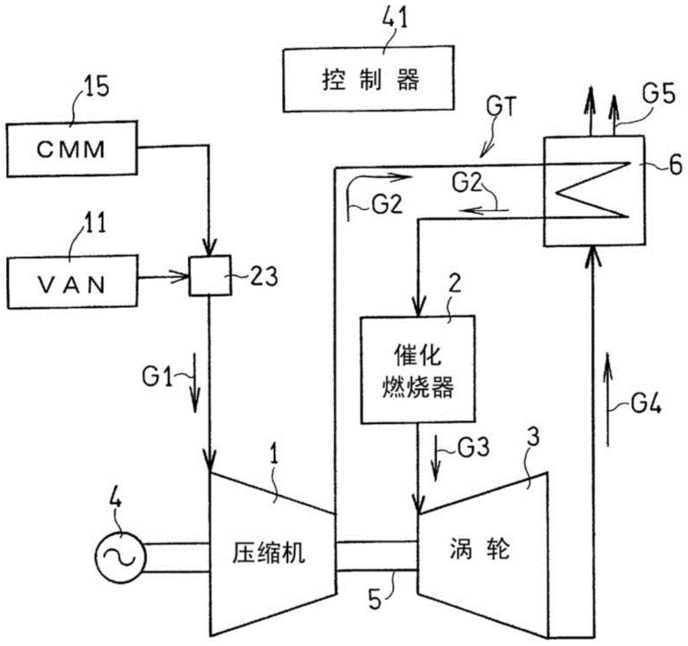
[0027] Preferred embodiments of the present invention will be described below with reference to the drawings. figure 1 It is a block diagram showing a schematic configuration of a gas turbine engine GT provided with a flow velocity distribution equalizing device according to an embodiment of the present invention. In this embodiment, a gas turbine engine GT using a lean fuel as described later is exemplified. This gas turbine engine GT has a compressor 1 , a catalytic combustor 2 containing a catalyst such as platinum or palladium, and a turbine 3 . The generator 4 is driven by the output of the gas turbine engine GT.

[0028] As the low-calorie fuel gas used in the gas turbine engine GT, the following fuel gas can be used. For example, VAM (Ventilation Air Methane; Coal Mine Ventilation Methane) produced in a coal mine is supplied from the VAN supply source 11, and CMM (Coal Mine Methane; Coal Mine Methane) having a combustible component (methane) concentration higher than t...


PUM


Abstract

An apparatus for equalizing flow velocity distribution of a fuel gas supplied into a catalytic combustor includes a rectification vane and a rectification plate in an inlet chamber of the catalyst combustor. The inlet chamber has a round transverse sectional shape and includes an inflow port that allows the fuel gas to inflow radially, and an outflow port for discarding the fuel gas axially. The rectification vane has a front edge oriented towards the inflow port, and a rectifying surface ramified from the front edge so as to extend towards a cylindrical inner wall surface of the inlet chamber such that swirling flow of the fuel gas flown into the inlet chamber, that flows towards the inflow port along the cylindrical inner wall surface, is generated. The rectification plate is located at the outflow port and has openings for allowing the fuel gas to flow therethrough.

Description

[0001] related application [0002] This application claims the priority of Japanese Patent Application No. 2011-288019 for which it applied on December 28, 2011, The content is taken in as a part as a part by reference here. technical field [0003] The invention relates to a device for homogenizing the flow velocity distribution of gases flowing into a catalytic combustor of a gas turbine engine. Background technique [0004] Catalytic combustors installed in gas turbine engines have the following advantages over existing technologies in that when the inflow gas is combusted by a catalytic reaction, NOX is hardly emitted, and it is possible to oxidize low-concentration methane that is normally not combustible and emitted to the atmosphere ; It has the advantage of being able to cope with environmental problems such as low pollution and global warming countermeasures. On the other hand, catalytic burners have disadvantages such as high price and short life. [0005] Espec...

Claims


Application Information

Patent Timeline
Patent Type & Authority Applications(China)
IPC IPC(8): F23R3/40F23D14/18
CPCF23R3/04F23L15/00F02C7/22F23R3/40Y02E20/34
Inventor 堂浦康司绪方正裕棚木航介
Owner KAWASAKI HEAVY IND LTD
Why Eureka
Try Eureka