A Pneumatic Amplified Tie Rod Press

A press and booster technology, applied in the direction of presses, stamping machines, manufacturing tools, etc., can solve the problems of poor mechanical properties of presses, ineffective acceleration of hydraulic cylinders, and large impact forces, etc., to meet the requirements of strength and Rigidity requirements, superior comprehensive performance, conducive to the effect of shock absorption and noise reduction

Active Publication Date: 2016-04-20
JIANGSU HANNA PUMP IND CO LTD
View PDF7 Cites 0 Cited by
  • Summary
  • Abstract
  • Description
  • Claims
  • Application Information

AI Technical Summary

Problems solved by technology

However, the pneumatically driven press has a significant disadvantage, that is, the working pressure of the press is low due to the easy leakage of gas, usually only 0.4-0.7MPa, which cannot meet the occasions requiring large output force
[0003] In the prior art, the power system of the pneumatic press is generally placed on the top, that is, the power system is placed above the worktable to drive the punch to move up and down for stamping. Some pneumatic presses are not symmetrical in structure, which will cause the center of gravity of the press to On the high side, the mechanical properties of the press are poor and the stability is poor
In addition, when the press is working, its impact force acts on the workbench, so that the workbench and the base need to bear a large impact force, resulting in greater noise. At the same time, this also requires the base of the press to have higher strength and rigidity. Therefore, to a certain extent, the overall size of the press is too large
[0004] At present, the widely used hydraulic press has large output force, small size and high control precision, but its speed is slow and the working stroke is small, resulting in low production efficiency, and the system maintenance is difficult, and the oil is easy to leak. higher cost
In addition, the oil of the traditional hydraulic press achieves speed-up through the external differential circuit, but the pressure loss of the oil in the external differential circuit is relatively large, which leads to the ineffective speed-up effect of the hydraulic cylinder and increases the number of pipelines. and connection costs

Method used


Image

  • A Pneumatic Amplified Tie Rod Press
  • A Pneumatic Amplified Tie Rod Press
  • A Pneumatic Amplified Tie Rod Press

Examples


Embodiment Construction

[0018] The technical solutions of the present invention will be further described below in conjunction with the accompanying drawings and specific embodiments.

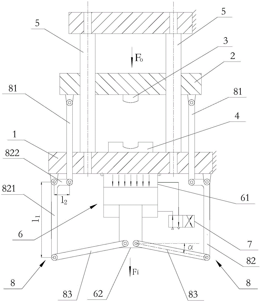
[0019] see figure 1 The shown press includes a workbench 1 fixedly arranged on the frame, an upper mold assembly that is vertically lifted and lowered on the frame and located above the workbench 1, and the upper mold assembly includes an up-and-down lift The sliding seat 2 arranged on the frame, the upper mold 3 fixedly arranged under the sliding seat 2, the lower mold 4 matched with the upper mold 3 is fixedly arranged on the workbench 1, and the upper part of the workbench 1 is provided with multiple A guide post 5 extending in the vertical direction provides a guide for the sliding seat 2 to slide in the up and down direction.

[0020] The press also includes a cylinder 6 fixedly installed under the workbench 1. The cylinder 6 includes a cylinder body 61 and a piston rod 62 that is axially telescopic relative to ...


PUM


Abstract

The invention discloses a power underneath type pull rod press. According to the pull rod press, a motor and a lead screw nut are combined to serve as a power system which is placed below a workbench, and meanwhile a boost mechanism is arranged between an upper die assembly and the nut so that the upper die assembly can output larger output force, and workpieces can be formed and machined conveniently. Thus, while certain tonnage of the press is required, a motor with low power can be adopted, energy is saved, and cost is reduced. Meanwhile, due to the underneath power system, the stress condition of a base below the workbench is improved, the base of the press can meet the requirements for strength and rigidity more easily, shock absorption and noise reduction are facilitated, the gravity center of the press is lowered, and thus the dynamic performance of the press is improved. Compared with a structure in the prior art, the structural size of the press can be substantially reduced, the pull rod press is large in impact force, high in working efficiency and energy utilization rate, low in working noise and superior in comprehensive performance.

Description

technical field [0001] The invention relates to a pneumatic booster tie rod press. Background technique [0002] Pneumatic press is a kind of pressure processing equipment that uses air as the working medium to shape the billet. It is widely used in punching, bending, stretching and extrusion processes, and can directly produce finished or semi-finished products. However, the pneumatically driven press has a significant disadvantage, that is, the working pressure of the press is low due to the easy leakage of gas, usually only 0.4-0.7MPa, which cannot meet the occasions requiring large output force. [0003] In the prior art, the power system of the pneumatic press is generally placed on the top, that is, the power system is placed above the worktable to drive the punch to move up and down for stamping. Some pneumatic presses are not symmetrical in structure, which will cause the center of gravity of the press to On the high side, the mechanical properties of the press are ...

Claims


Application Information

Patent Timeline
Patent Type & Authority Patents(China)
IPC IPC(8): B30B1/38B30B1/10
Inventor 王明娣王金娥汤攀飞
Owner JIANGSU HANNA PUMP IND CO LTD
Why Eureka
Try Eureka