
System and method for efficiently removing dust in flue gas of coal-fired power plant

A technology of coal-fired power plants and dust removal systems, applied in the field of exhaust gas purification, can solve problems such as failure to meet emission standards, failure to meet emission standards, excessive dust emissions, etc., to reduce investment and plant power consumption, reduce the number of stages and power plants Power utilization rate, effect of reducing clogging and equipment wear

Inactive Publication Date: 2014-08-20
彭维明
View PDF13 Cites 2 Cited by
  • Summary
  • Abstract
  • Description
  • Claims
  • Application Information

AI Technical Summary

Problems solved by technology

Patent document CN200710092757.8 discloses a pre-cyclone pre-dust removal SCR flue gas denitrification process, but its dust removal effect is not good, it is not suitable for such a huge flue gas flow in coal-fired power plants, and cannot meet the emission standards
[0004] Although the flue gas from coal-fired power plants has been treated accordingly, due to backward technology and incomplete removal, the flue gas discharged from coal-fired power plants still cannot meet the emission standards, especially the amount of dust in the flue gas has seriously exceeded the standard

Method used


Image

  • System and method for efficiently removing dust in flue gas of coal-fired power plant
  • System and method for efficiently removing dust in flue gas of coal-fired power plant
  • System and method for efficiently removing dust in flue gas of coal-fired power plant

Examples


Embodiment Construction

[0080] In order to make the purpose, technical solution and advantages of the present invention clearer, the following examples will be used in conjunction with the accompanying drawings to further describe the high-efficiency dust removal system for coal-fired power plant flue gas of the present invention in detail. It should be understood that the specific embodiments described here are only used to explain the present invention, not to limit the present invention.

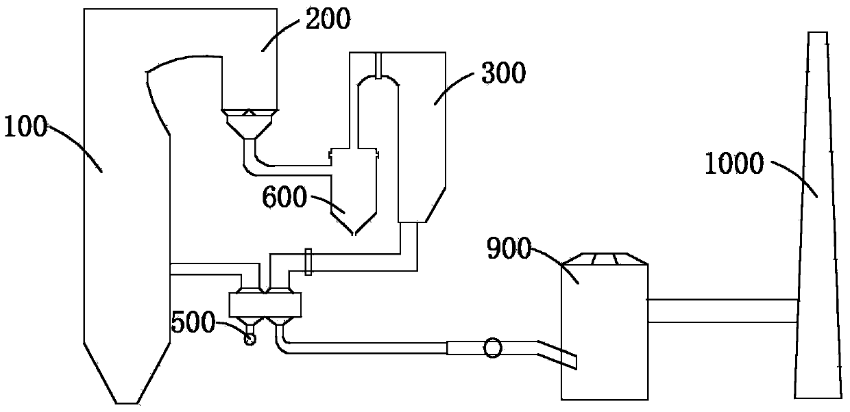
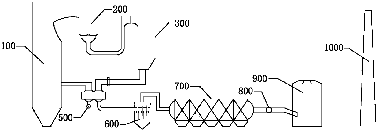
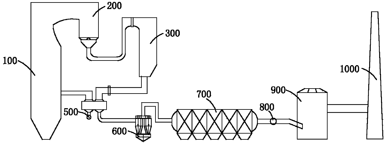
[0081] At present, the removal of dust from the flue gas emitted by coal-fired power plants cannot meet the standards required by the state, causing a large amount of dust to float in the air, resulting in the occurrence of haze weather. Due to the backwardness of the existing technology, the predetermined technical effect cannot be achieved. Therefore, , this system, refer to figure 1 , a high-efficiency dust removal system for flue gas of coal-fired power plants, used to remove dust from the flue gas of coal-f...


PUM


Abstract

The invention provides a system for efficiently removing dust in flue gas of a coal-fired power plant. The system is arranged between a boiler and a chimney of the coal-fired power plant, and used for removing dust in the flue gas discharged from the coal-fired power plant. The system comprises an economizer, a denitration reactor, an air preheater and a desulfurizing tower which are communicated sequentially, wherein the economizer is communicated with the boiler, and the desulfurizing tower is communicated with the chimney. The system further comprises a multi-tube type cyclone separator, wherein the multi-tube type cyclone separator is arranged between the economizer and the chimney and used for removing dust in the flue gas of the coal-fired power plant. The invention further provides a method for efficiently removing dust in the flue gas of the coal-fired power plant. The system for efficiently removing dust in the flue gas of the coal-fired power plant is reasonable in design, and for the flue gas discharged from the coal-fired power plant, the multi-tube type cyclone separator is arranged between the economizer and the chimney to remove dust from the flue gas; moreover, the multi-tube type cyclone separator can meet the requirement for purification efficiency of the system, and the flue gas discharged from the coal-fired power plant can reach the corresponding discharging standard.

Description

technical field [0001] The invention relates to the technical field of waste gas purification, in particular to a high-efficiency dust removal system and method for flue gas of a coal-fired power plant. Background technique [0002] With the increasingly prominent problems of environmental pollution in our country, especially the haze weather has brought increasingly serious impact on people's life and health, it is necessary to further reduce the discharge of pollutants and improve discharge standards. Therefore, future coal-fired power plants will have to meet emission standards for gas-fired power generation. [0003] The flue gas coming out of the coal-fired power plant boiler after combustion must go through dust removal, desulfurization and denitrification, and the flue gas that meets the emission standard can be discharged into the atmosphere. From the boiler, the flue gas passes through the economizer, denitrification reactor, air preheater, booster fan, desulfuriza...

Claims


Application Information

Patent Timeline
IPC IPC(8): F23J15/00
Inventor 彭维明
Owner 彭维明
Learn More