Automatic compression joint device for wires
A crimping device and automatic technology, applied in the direction of connection, overhead line/cable equipment, line/collector parts, etc., can solve the problems of impact of crimping effect, large number of laborers, long time consumption, etc., to achieve convenient operation, reduce The effect of labor intensity and mature processing technology
- Summary
- Abstract
- Description
- Claims
- Application Information
AI Technical Summary
Problems solved by technology
Method used
Image
Examples
Embodiment Construction
[0029] The specific implementation manners of the present invention will be further described in detail below in conjunction with the accompanying drawings.
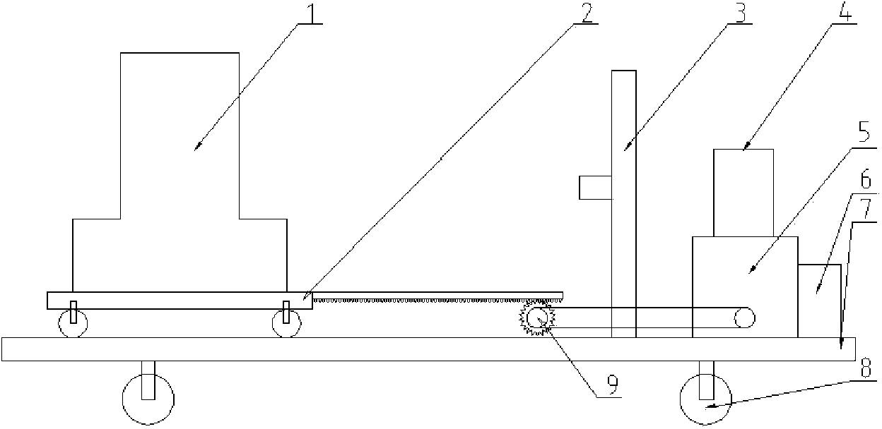
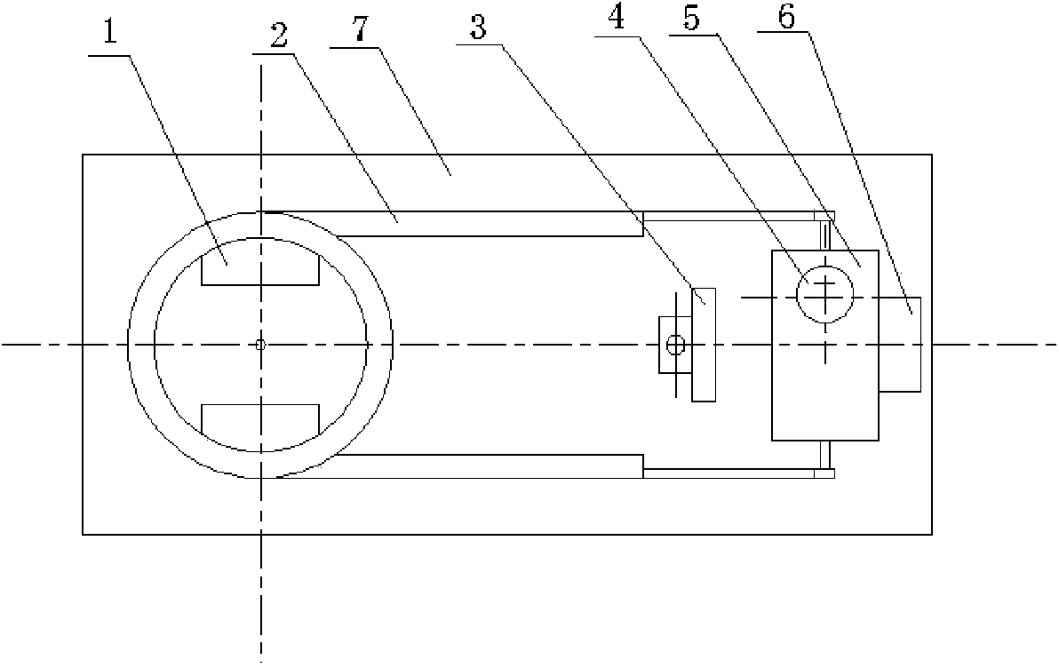
[0030] This embodiment takes the wire automatic crimping device as an example, such as Figure 1 to Figure 5 As shown, the wire automatic crimping device provided by the embodiment of the present invention includes: a crimping mechanism 1, a transmission bracket 2, a fixing mechanism 3, a control module 4, a motor 5, a hydraulic pump 6, a supporting plate 7, a universal wheel 8, Transmission gear 9, base 10, left side wall 11, right side wall 12, positioning hole 13, crimping die 14, upper crimping die 15, lower crimping die 16, positioning key 17. The crimping mechanism 1, the fixing mechanism 3, the motor 5 and the hydraulic pump 7 are arranged vertically on the supporting plate 7 in sequence along the same axial direction. The crimping mechanism 1 is connected with the hydraulic pump 6 through pipelines. 7. A transmi...
PUM
 Abstract
Description
Claims
Application Information
 - Generate Ideas
- Intellectual Property
- Life Sciences
- Materials
- Tech Scout
- Unparalleled Data Quality
- Higher Quality Content
- 60% Fewer Hallucinations
Browse by: Latest US Patents, China's latest patents, Technical Efficacy Thesaurus, Application Domain, Technology Topic, Popular Technical Reports.
© 2025 PatSnap. All rights reserved.Legal|Privacy policy|Modern Slavery Act Transparency Statement|Sitemap|About US| Contact US: help@patsnap.com


