
Needle valve component for fuel injection device

A technology of fuel injection and needle valve, which is applied in the direction of fuel injection devices, charging systems, engine components, etc., can solve the problems of not being able to take into account fuel consumption and pollutant discharge, and can not meet the oil-gas mixing conditions, so as to improve the oil-gas mixing conditions, Improve the utilization rate of air in the cylinder and avoid collision with the cylinder wall

Active Publication Date: 2014-08-13
JIANGSU UNIV +1
View PDF6 Cites 6 Cited by
  • Summary
  • Abstract
  • Description
  • Claims
  • Application Information

AI Technical Summary

Problems solved by technology

However, this fuel injection device cannot meet the oil-air mixing conditions under different combustion modes, resulting in the inability to take into account the control of fuel consumption and pollutant emissions under different conditions, and requires a large gap between the needle valve and the valve hole in the axial direction and at the end. High fit accuracy

Method used


Image

  • Needle valve component for fuel injection device
  • Needle valve component for fuel injection device
  • Needle valve component for fuel injection device

Examples


Embodiment Construction

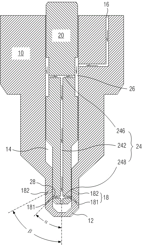
[0048] In order to have a clearer understanding of the technical features, purposes and effects of the invention, the specific implementation is now described with reference to the accompanying drawings. The accompanying drawings are only used to help understanding, and do not represent the actual structure and true proportion of the product. The same labels in each figure represent the same part.

[0049] In this article, "schematic" means "serving as an example, example or illustration", and any illustration or implementation described as "schematic" should not be interpreted as a more preferred or more advantageous Technical solutions. In this article, "first", "second", and "third" are only used to distinguish each other, rather than expressing their importance and the like. In this article, "communication" can mean the direct communication between the two, or the indirect communication through a third party.

[0050] Such as figure 2 As shown, the needle valve assembl...


PUM


Abstract

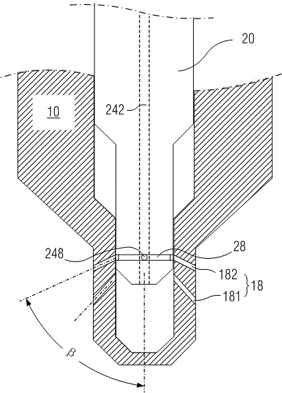
The invention discloses a needle valve component for a fuel injection device. The needle valve component comprises a valve body (10) and a needle valve (20). The valve body is provided with a valve body end (12), a valve hole (14), an oil inlet channel (16) and an oil injection hole (18). The oil injection hole comprises a first group of oil injection holes (181) and a second group of oil injection holes (182), wherein the first jet angles of the first group of oil injection holes are smaller than the second jet angles of the second group of oil injection holes, and the communicating positions of the first group of oil injection holes and the valve hole are closer to the valve body end than the communicating positions of the second group of oil injection holes and the valve hole. The needle valve can reciprocate in the valve hole and comprises an oil inlet ring groove (26), an oil outlet ring groove (28) and an oil supply channel (24) for communicating the oil inlet ring groove and a first oil outlet ring groove. The first oil outlet ring groove is respectively communicated with the first group of oil injection holes and the second group of oil injection holes, the fuel oil is sprayed at different jet angles so as to adapt to oil-gas mixing under different loads, the oil consumption and discharge under the different conditions are both considered, and the needle valve component has the advantages of simple structure and convenience for processing.

Description

technical field [0001] The invention relates to a needle valve assembly of a fuel injection device, in particular to a needle valve assembly of a fuel injection device for a diesel engine. Background technique [0002] The traditional combustion of diesel engines is a high temperature combustion HTC (High Temperature Combustion) mode, which is very easy to form NOx and PM, and NOx and PM show an obvious opposite relationship. How to reduce NOx and PM emissions at the same time is the focus of improving diesel engine emissions. [0003] Premixed Charge Compression Ignition Combustion PCCI (Premixed Charge Compression Ignition) allows a richer mixture region in the cylinder, as long as the fuel-air equivalence ratio in the rich mixture region is less than 2, it can avoid the formation of exhaust carbon particles (soot) emissions Of course, this combustion method must ensure that the maximum combustion temperature does not exceed 2200K to avoid the NOx generation area. When th...

Claims


Application Information

Patent Timeline
Patent Type & Authority Applications(China)
IPC IPC(8): F02M61/10F02M61/18
Inventor 尹必峰王佳何建光贾和坤徐毅孙建中熊飞王伟峰
Owner JIANGSU UNIV
Learn More