Eureka AIR delivers breakthrough ideas for toughest innovation challenges, trusted by R&D personnel around the world.

A microbial fuel cell coupled electrode biofilm phosphorus and nitrogen removal system and its application

A biofilm system and fuel cell technology, applied in biological water/sewage treatment, water pollutants, water/sludge/sewage treatment, etc., can solve the problem of low phosphorus removal efficiency, low power generation power of microbial fuel cells, and general removal efficiency. and other problems, to achieve the effect of simple process flow, small footprint, and improved power production efficiency

Inactive Publication Date: 2015-07-29
SOUTHEAST UNIV
View PDF4 Cites 2 Cited by
  • Summary
  • Abstract
  • Description
  • Claims
  • Application Information

AI Technical Summary

Problems solved by technology

[0004] However, microbial fuel cells have low power generation and can only output low-voltage currents
At present, a lot of research has been carried out on the principle of microbial fuel cells, but the application of microbial fuel cells is still in the exploratory stage.
In addition, the removal efficiency of nitrogen by microbial fuel cells is average, and the removal efficiency of phosphorus is very low, and the effect of phosphorus and nitrogen removal needs to be further strengthened

Method used


Image

  • A microbial fuel cell coupled electrode biofilm phosphorus and nitrogen removal system and its application
  • A microbial fuel cell coupled electrode biofilm phosphorus and nitrogen removal system and its application
  • A microbial fuel cell coupled electrode biofilm phosphorus and nitrogen removal system and its application

Examples


Embodiment 1

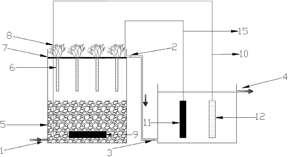
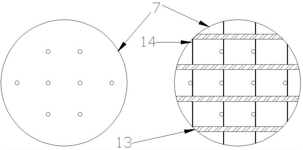
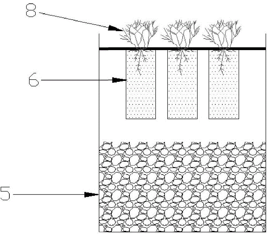
[0027] Such as figure 1 As shown, an ecological microbial fuel cell coupled electrode biofilm system that strengthens phosphorus and nitrogen removal is composed of an E-MFC subsystem and a BER subsystem, and the E-MFC subsystem includes an E-MFC reaction tank, E-MFC water inlet 1 on the bottom side of the E-MFC reaction tank, E-MFC water outlet 2 on the top side of the E-MFC reaction tank, non-conductive substrate laid on the bottom of the E-MFC reaction tank 5. Place the E-MFC anode electrode 9 in the non-conductive matrix 5, the E-MFC cathode electrode 7 positioned at the top of the E-MFC reaction tank, the plant 8 planted on the surface of the E-MFC cathode electrode 7, and the BER subunits The system includes a BER reaction tank, a BER water inlet 3 located on the bottom side of the BER reaction tank, a BER water outlet 4 located on the top side of the BER reaction tank, a BER anode electrode 11 and a BER cathode electrode 12 located in the BER reaction tank , the E-MFC ...

Embodiment 2

[0030] Basically the same as in Example 1, the difference is that the liquid level of the BER reaction tank is 10 cm lower than that of the E-MFC reaction tank. The non-conductive matrix 5 is shale.

Embodiment 3

[0032] Basically the same as in Example 1, the difference is that the liquid level of the BER reaction tank is 15 cm lower than that of the E-MFC reaction tank. The non-conductive matrix 5 is a mixture of shale and gravel.


PUM


Abstract

The invention discloses an ecological type microbial fuel cell coupling electrode bio-membrane system with enhanced nitrogen and phosphorus removal. The system consists of an E-MFC subsystem and a BER subsystem, wherein the E-MFC subsystem comprises an E-MFC reaction tank, an E-MFC water inlet, an E-MFC water outlet, a non-conductive matrix, an E-MFC anode electrode, an E-MFC cathode electrode and plants; the BER subsystem comprises a BER reaction tank, a BER water inlet, a BER water outlet, a BER anode electrode and a BER cathode electrode. The invention also discloses an ecological type MFC coupling BER enhanced sewage nitrogen and phosphorus removal method, and also discloses an application of the system in enhancement of sewage treatment. The ecological type MFC coupling BER makes full use of electric energy generated by MFC to enhance the nitrogen and phosphorus removal effect of BER, so that chemical medicaments are not used, and energy sources are saved; the microbial fuel cell coupling electrode bio-membrane nitrogen and phosphorus removal system is a low-carbon water pollution control technology.

Description

technical field [0001] The invention belongs to the field of energy and water treatment, in particular to a microbial fuel cell coupling electrode biofilm dephosphorization and denitrification system and its application. Background technique [0002] In recent years, with the widespread use of chemical fertilizers, detergents, pesticides and various other chemical substances, the content of organic matter, nitrogen, and phosphorus in urban sewage has continued to increase, and the power consumption for sewage treatment is huge. At present, one of the hot spots in the field of water pollution control is to apply the principle of microbial electricity generation to the sewage treatment process, and use microbial fuel cells (Microbial Fuel Cells, MFCs) to harvest electricity while purifying sewage, which can alleviate energy problems to a certain extent. . [0003] Compared with other existing technologies that use organic matter to generate energy, microbial fuel cells have o...

Claims


Application Information

Patent Timeline
Patent Type & Authority Patents(China)
IPC IPC(8): C02F3/34C02F101/16
Inventor 宋海亮黄诗蓓李先宁吴磊杨小丽
Owner SOUTHEAST UNIV
Why Eureka
Eureka Blog
Learn More