A belt polishing machine
An abrasive belt polishing and polishing belt technology, applied in the field of machinery, can solve the problems of clear accumulation, heavy quality, and inability to clean debris, etc., and achieve good results.
- Summary
- Abstract
- Description
- Claims
- Application Information
AI Technical Summary
Problems solved by technology
Method used
Image
Examples
Embodiment 1
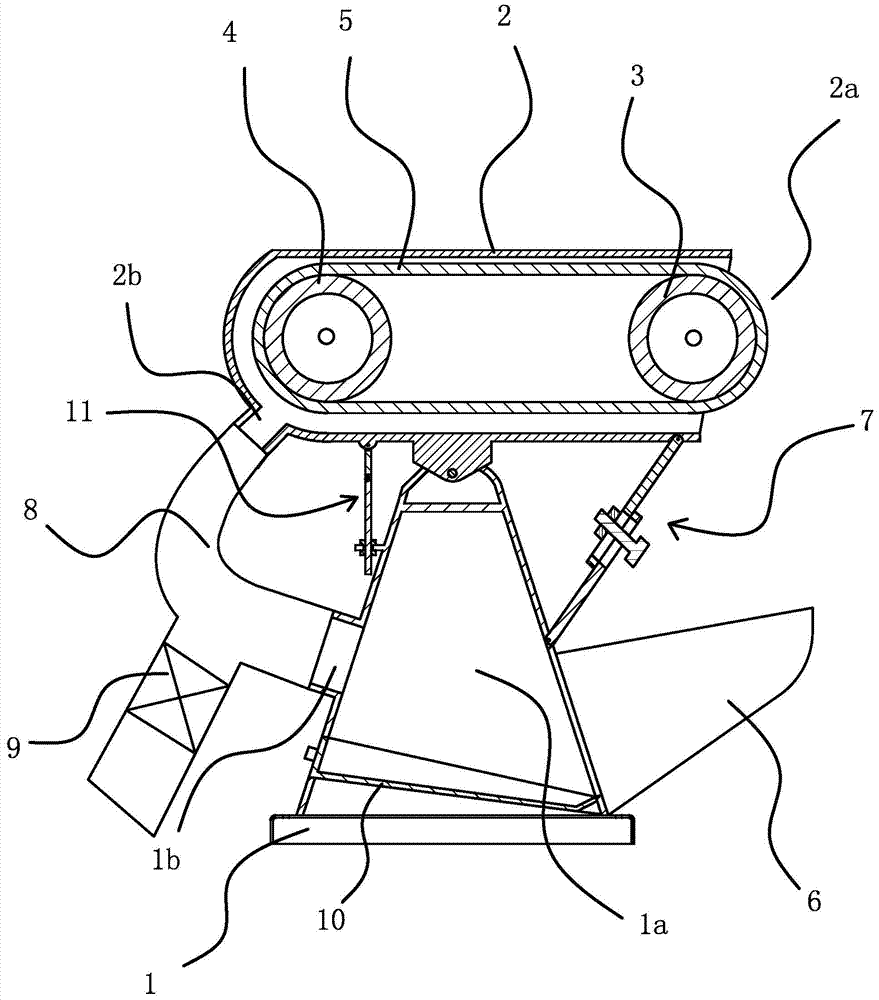
[0025] Such as figure 1 As shown, the abrasive belt polishing machine includes a frame 1 and a workbench 2 arranged on the frame 1, and the workbench 2 is provided with a driving wheel 3, a driven wheel 4, and a polishing belt sleeved on the driving wheel 3 and the driven wheel 4. With 5, the lower part of the workbench 2 is hinged on the frame 1 and can rotate relative to the frame 1. Turning the worktable 2 can raise or lower the operation port 2a, which is convenient for processing various complex workpieces. The workbench 2 is provided with an operation port 2a for the workpiece to contact the polishing belt 5, and the frame 1 below the operation port 2a is connected with a dust collecting bucket 6, and the workbench 2 and the frame 1 are connected with a length that can be freely expanded and retracted. The dust generated during the polishing operation can be guided into the baffle mechanism 7 of the dust collecting hopper 6 . The dust collecting hopper 6 is connected t...
Embodiment 2
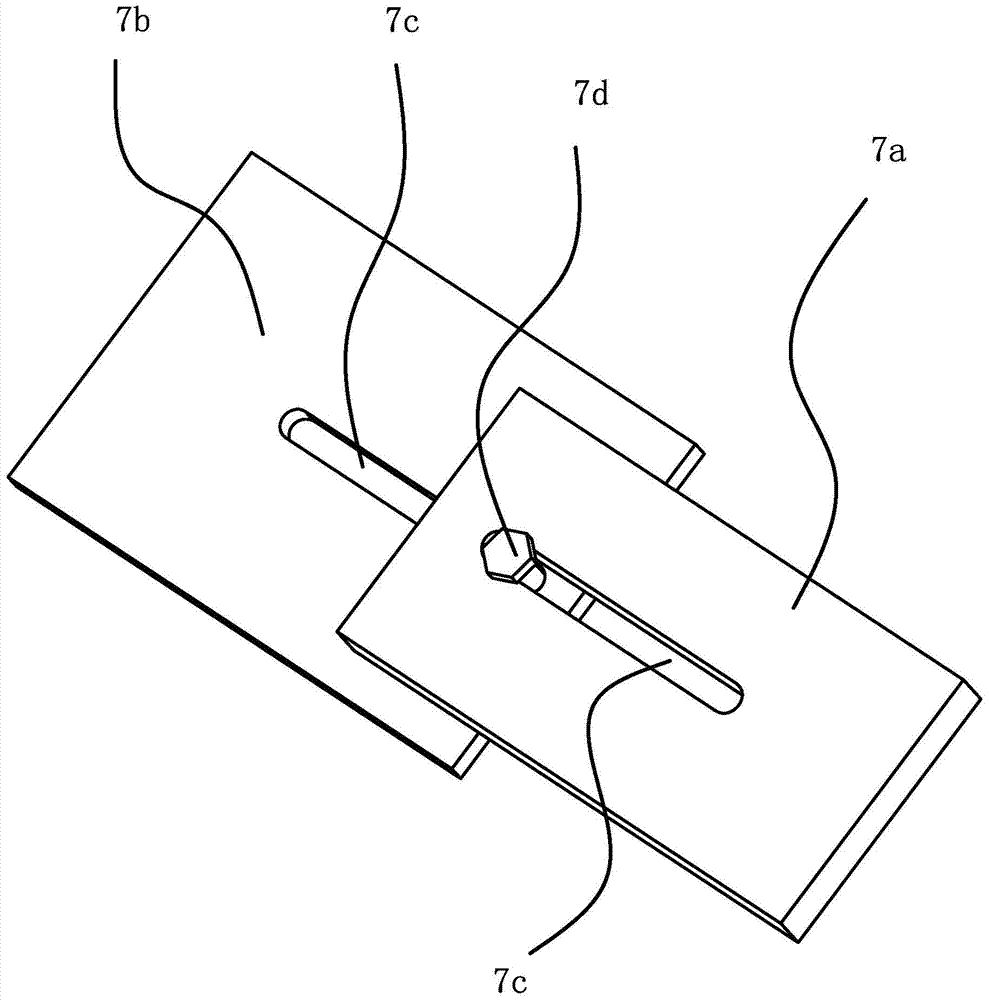
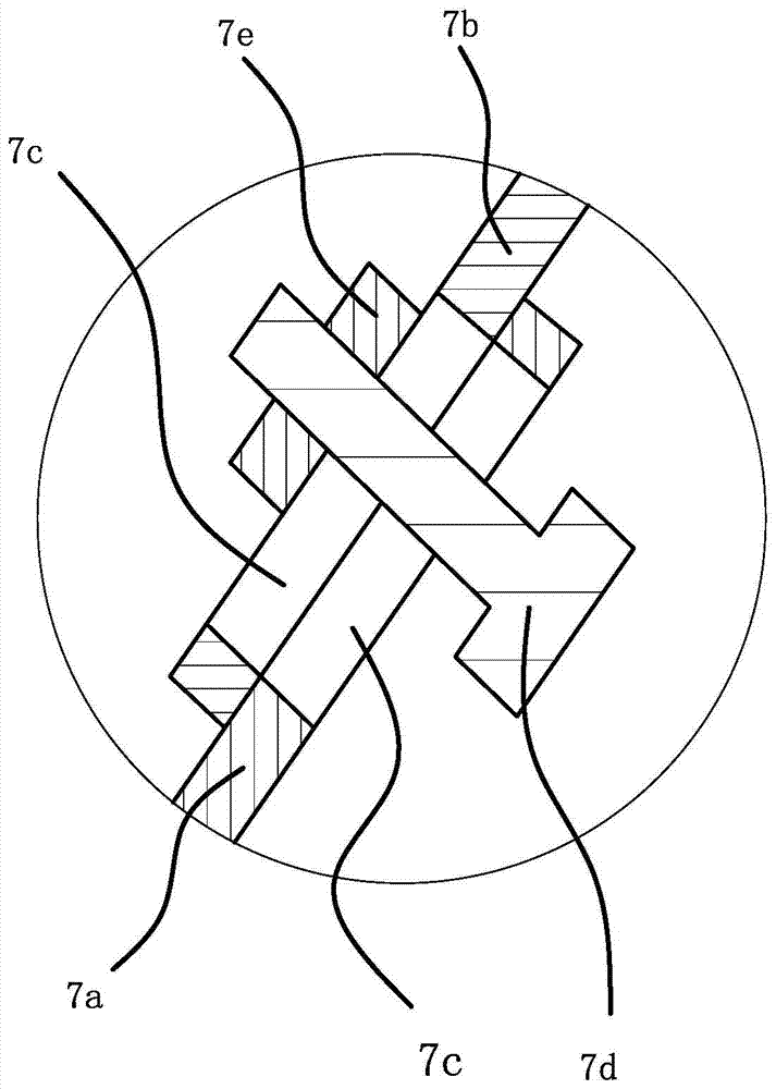
[0030] Such as Figure 4 As shown, the difference of Embodiment 1 lies in the baffle mechanism 7, and the baffle mechanism 7 of this embodiment only needs to open a guide groove 7c on a connecting plate. The baffle plate mechanism 7 comprises a connecting plate one 7a hinged on the lower edge of the operating port and a connecting plate two 7b hinged on the side of the frame 1, the connecting plate one 7a and the connecting plate two 7b are attached to each other, and the connecting plate one 7a is provided with The elongated guide groove 7c, the length direction of the guide groove 7c is the same as the expansion and contraction direction of the baffle plate mechanism 7, the connecting plate 2 7b is fixed with a fixing bolt 7d, the fixing bolt 7d passes through the guide groove 7c and is screwed at the exit end There is a fixing nut 7e. The fixing bolt 7d fixed on the connecting plate 2 7b slides along the guide groove 7c to realize the expansion and contraction function of ...
Embodiment 3
[0032] Such as Figure 5 As shown, it is another alternative method of the baffle mechanism 7, the baffle mechanism 7 includes a connecting plate 1 7a hinged on the lower edge of the operation port and a connecting plate 2 7b hinged on the side of the frame 1, the connecting plate 1 7a and The two connecting plates 7b are attached to each other, the two sides of the connecting plate one 7a have inwardly rolled flanges 7f, and the two sides of the connecting plate 7b are respectively embedded in the two flanges 7f and slide along the flanges 7f.
PUM
 Abstract
Description
Claims
Application Information
 - Generate Ideas
- Intellectual Property
- Life Sciences
- Materials
- Tech Scout
- Unparalleled Data Quality
- Higher Quality Content
- 60% Fewer Hallucinations
Browse by: Latest US Patents, China's latest patents, Technical Efficacy Thesaurus, Application Domain, Technology Topic, Popular Technical Reports.
© 2025 PatSnap. All rights reserved.Legal|Privacy policy|Modern Slavery Act Transparency Statement|Sitemap|About US| Contact US: help@patsnap.com


