
Active matrix image sensing panel and active matrix image sensing device

An image sensing and active matrix technology, applied in radiation control devices, etc., can solve problems such as source leakage, sensing distortion, and image sensing distortion, and achieve the effect of increasing critical voltage and avoiding image sensing distortion

Active Publication Date: 2014-08-06
INNOCARE OPTOELECTRONICS CORP
View PDF6 Cites 2 Cited by
  • Summary
  • Abstract
  • Description
  • Claims
  • Application Information

AI Technical Summary

Problems solved by technology

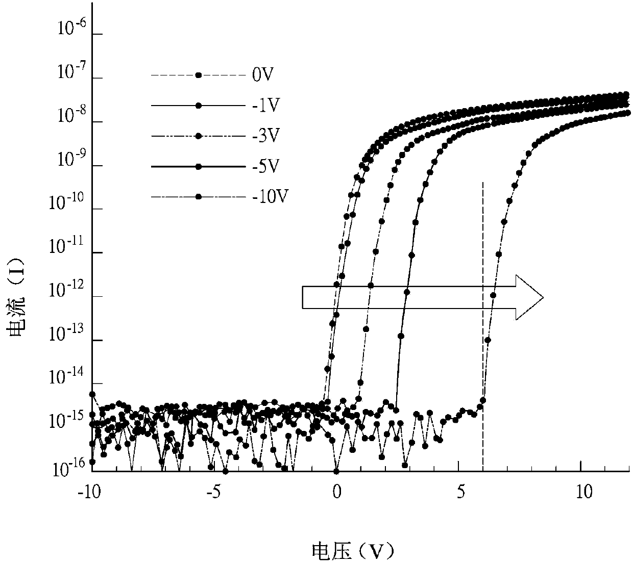
However, if the potential between the lower electrode and the source of the thin film transistor continues to drop due to high-intensity light irradiation, so that the potential difference between the gate and the source continues to rise, and is greater than the threshold voltage of the thin film transistor (Threshold voltage), Then the thin film transistor will be turned on and the source will start to leak to the data line. In this way, when the image processing module processes and obtains the image, it will cause the problem of sensing distortion
[0005] Therefore, how to provide an active matrix image sensing panel and device, which can avoid the leakage current phenomenon generated by the active matrix image sensing panel and device, and cause the problem of image sensing distortion has become one of the important issues.

Method used


Image

  • Active matrix image sensing panel and active matrix image sensing device
  • Active matrix image sensing panel and active matrix image sensing device
  • Active matrix image sensing panel and active matrix image sensing device

Examples


Embodiment Construction

[0049] The active matrix image sensing panel and device according to preferred embodiments of the present invention will be described below with reference to related drawings, wherein the same elements will be described with the same reference symbols.

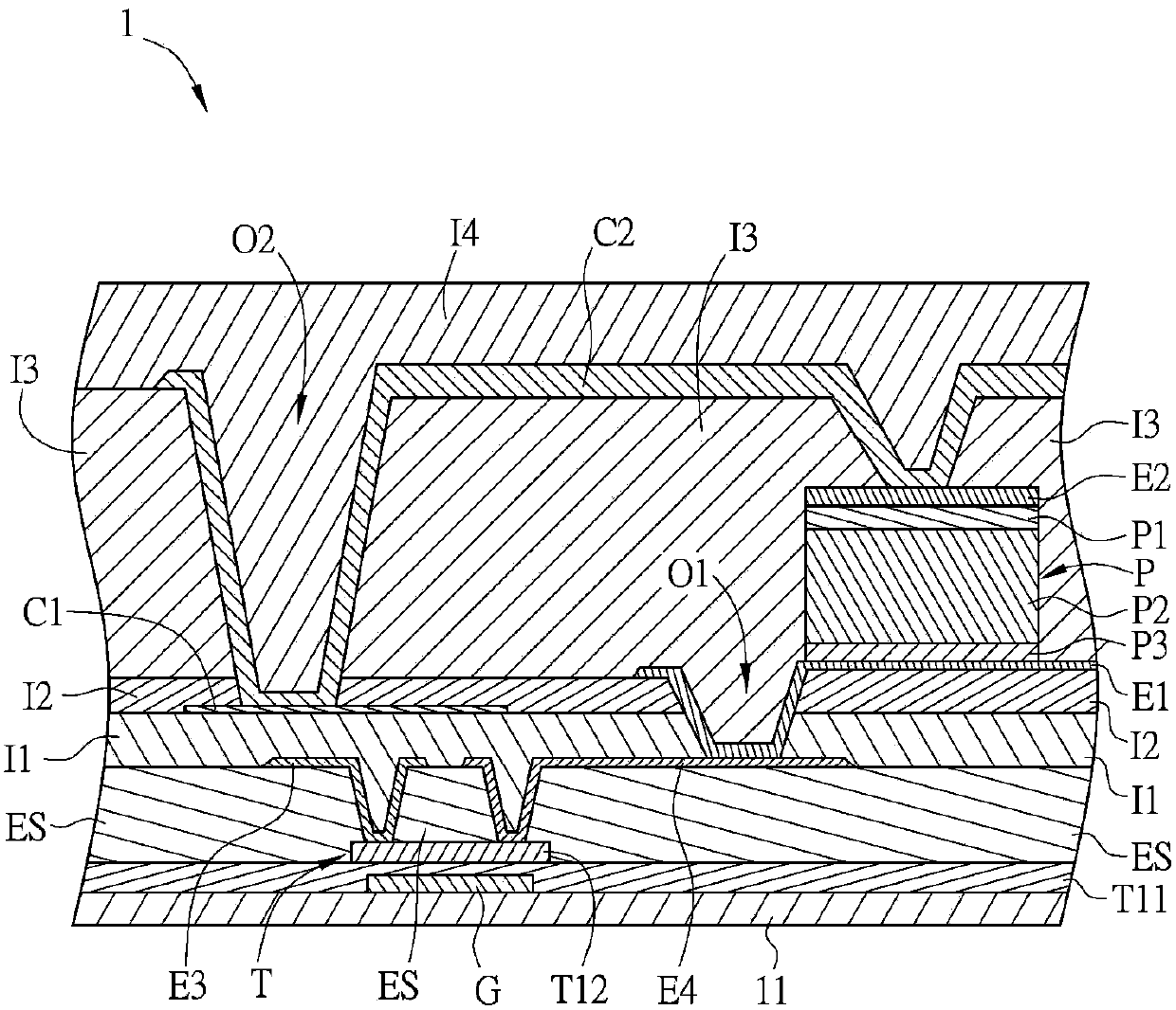
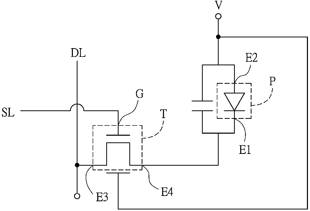
[0050] Please also refer to Figure 1A and Figure 1B As shown, among them, Figure 1A It is a schematic structural diagram of an image sensing pixel in an active matrix image sensing panel 1 according to a preferred embodiment of the present invention, and Figure 1B for Figure 1A The equivalent circuit diagram of the image sensor pixel.

[0051] The active matrix image sensing panel 1 includes a plurality of image sensing pixels disposed on a substrate 11 . In practice, the substrate 11 can be a light-transmitting material, such as glass, quartz or the like, plastic, rubber, glass fiber or other polymer materials, preferably a borate alkali-free glass substrate ( aluminum silicate glass substrate). The substrate 11 can a...


PUM


Abstract

The invention discloses an active matrix image sensing panel which comprises a substrate and an image sensing pixel. The image sensing pixel is arranged on the substrate and is provided with a scanning line, a data line, a photosensitive element and a thin-film transistor element. The data line and the scanning line are staggered on each other. The photosensitive element is provided with a first end point electrode and a second end point electrode, and voltages of the first end point electrode are higher than voltages of the second end point electrode. The thin-film transistor element is provided with a first electrode, a second electrode, a first gate and a second gate, the first electrode is electrically connected with the data line, the second electrode is electrically connected with the first end point electrode of the photosensitive element, the first gate is electrically connected with the scanning line, and the second gate is electrically connected with the first end point electrode or the second end point electrode of the photosensitive element. The invention further discloses an active matrix image sensing device. The active matrix image sensing panel and the active matrix image sensing device have the advantage that the problem of image sensing distortion due to current leakage of an existing active matrix image sensing panel and an existing active matrix image sensing device can be solved.

Description

technical field [0001] The present invention relates to an image sensing panel and device, in particular to an active matrix image sensing panel and device. Background technique [0002] Traditional X-ray imaging technology uses imaging film to receive X-ray exposure to form images, but in recent years, due to the development of semiconductor technology, X-ray imaging technology has also evolved to use flat-panel digital image sensing panels to image, that is, the so-called Digital radiography (digital radiography, DR) technology. [0003] The principle of digital radiography technology is briefly described as follows. When X-rays enter the image sensing device, they will first pass through a scintillator, which converts the X-rays into visible light, and then converts the sensed visible light into electrical signals through the photosensitive element, and then connects To the thin film transistor element, it is read from the data line, and then becomes an image after imag...

Claims


Application Information

Patent Timeline
Patent Type & Authority Applications(China)
IPC IPC(8): H01L27/146
Inventor 吴智濠周政旭
Owner INNOCARE OPTOELECTRONICS CORP
Learn More