
A Separable Rapid Prototyping Equipment for Selected Areas

A forming equipment and fast technology, applied in the direction of improving process efficiency, improving energy efficiency, etc., can solve the problem that the working focal length of the high-energy beam scanning system has a small variable range, and it is no longer possible to take out large parts and protect the cavity by opening the door through the side wall. Height increase and other issues, to achieve the effect of increasing the simplicity of operation, ensuring air tightness, and saving time

Active Publication Date: 2016-08-17
TECH LASER TECH SHANGHAI CO LTD
View PDF5 Cites 0 Cited by
  • Summary
  • Abstract
  • Description
  • Claims
  • Application Information

AI Technical Summary

Problems solved by technology

However, under the technical requirements of ensuring the powder is fully melted or sintered, the variable range of the working focal length of the high-energy beam scanning system is very small, and the height of the protection chamber is limited. Difficulties that need to be solved urgently in the development of selective melting and sintering rapid prototyping equipment

Method used


Image

  • A Separable Rapid Prototyping Equipment for Selected Areas
  • A Separable Rapid Prototyping Equipment for Selected Areas
  • A Separable Rapid Prototyping Equipment for Selected Areas

Examples


Embodiment Construction

[0038] The specific embodiments of the present invention will be further described below in conjunction with the accompanying drawings. It should be noted here that the descriptions of these embodiments are used to help understand the present invention, but are not intended to limit the present invention. In addition, the technical features involved in the various embodiments of the present invention described below can be combined with each other as long as they do not constitute a conflict with each other.

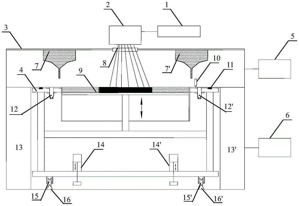
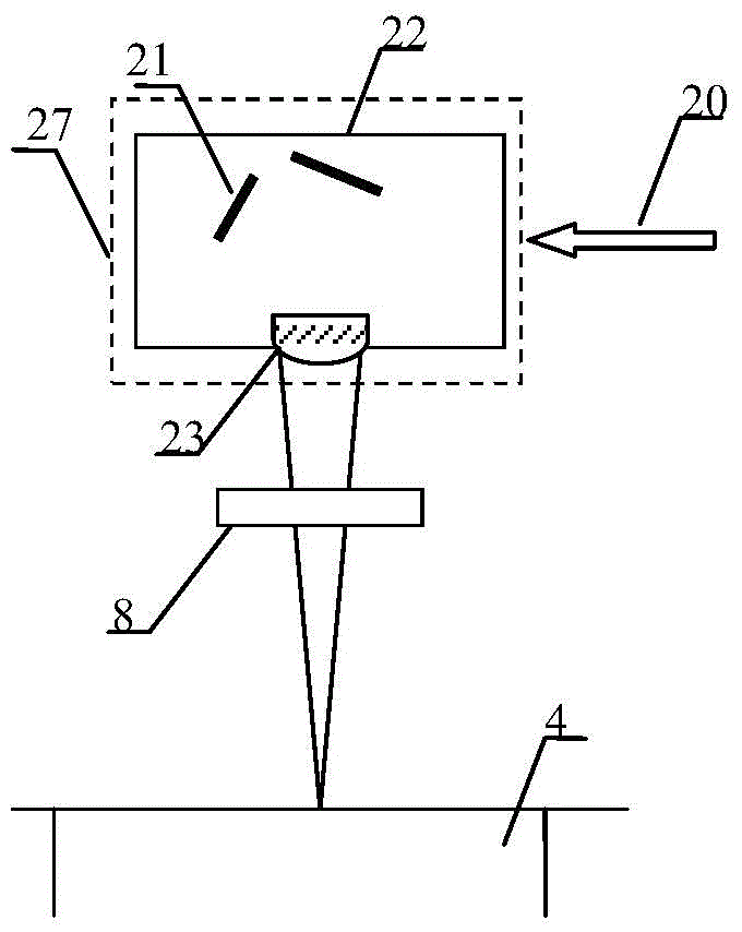
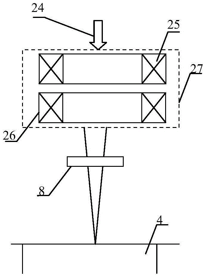
[0039] The selected area rapid prototyping equipment involved in the invention includes a high-energy beam generator group, a scanning system, a protection cavity, a cavity support, a forming machine tool, an atmosphere protection system and a control system. Among them, the coverage of the scanning system and the size of the forming cylinder in the forming machine are the core components for realizing large or extra large parts. The protective cavity, the support of th...


PUM


Abstract

The invention discloses a separable selective melting and sintering rapid forming device. The device mainly comprises a high-energy-beam generator set, a scanning system, a protection cavity, a cavity support, a forming machine tool, an atmosphere protection system and a control system, wherein the protection cavity, the forming machine tool and the cavity support are core assemblies of the device. The forming machine tool or the protection cavity is designed to be movable or rotatable, and the forming machine tool and the protection cavity can separate from each other; parts with any size and any shape can be manufactured without changing the forming precision or the complexity of the parts or the mechanical performance and can be conveniently taken out of the forming machine tool, and the operating efficiency is doubled. The device is particularly suitable for manufacturing parts with any complex shape, which are large or extra large or extra large in size in a certain direction.

Description

technical field [0001] The invention belongs to the field of rapid prototyping, and specifically relates to a separate selective melting and sintering rapid prototyping equipment. The formed parts can be metal, non-metal or composite materials of metal and non-metal. Background technique [0002] Additive Manufacturing technology (Additive Manufacturing), also known as 3D printing technology, is a new manufacturing technology based on the principle of layer-by-layer accumulation of discrete materials, based on the three-dimensional CAD model of the product, and the product prototype or parts are accumulated layer by layer through materials. [0003] The selective melting and sintering rapid prototyping technology based on powder coating can manufacture parts of almost any shape because it can use auxiliary structures and loose powder as support, and has attracted the most attention among many additive manufacturing technologies. Its basic working principle is to spread a cer...

Claims


Application Information

Patent Timeline
Patent Type & Authority Patents(China)
IPC IPC(8): B22F3/105B29C67/04
CPCY02P10/25
Inventor 王泽敏曾晓雁陈立新任昭
Owner TECH LASER TECH SHANGHAI CO LTD
Learn More